


10 - 22
10.3 Wiring
10.3.2 Connecting to the power supply module
10
LOADING AND INSTALLATION
10.3.2 Connecting to the power supply module
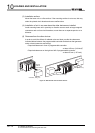
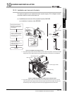
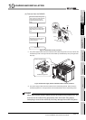
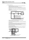
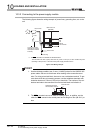
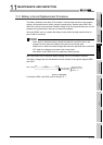
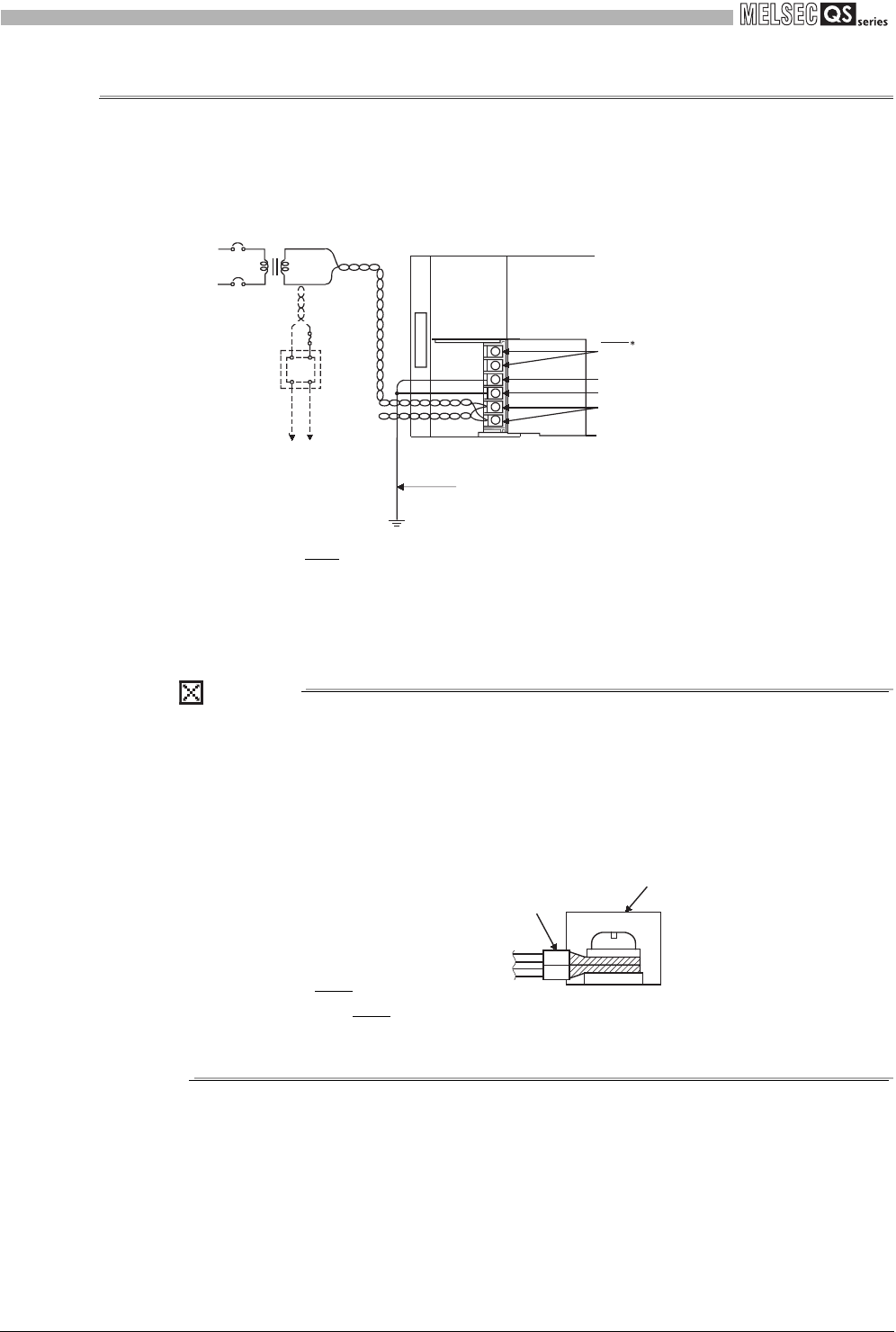
The following figure shows the wiring example of power lines, grounding lines, etc. to the
unit.
* 1: The ERR. terminal turns ON/OFF as described below.
The terminal turns OFF (opens) when the AC power is not input, a CPU module stop error
(including a reset) occurs, or the fuse of the power supply module is blown.
POINT
1. Use the thickest possible (max. 2 mm
2
(14 AWG)) wires for the 100/200 VAC
power cables. Be sure to twist these wires starting at the connection termi-
nals. For wiring a terminal block, be sure to use a solderless terminal. To pre-
vent short-circuit due to loosening screws, use the solderless terminals with
insulation sleeves of 0.8 mm (0.03 inch) or less thick. The number of the sol-
derless terminals to be connected for one terminal block are limited to 2.
2. The ERR
. terminal can not be used as a safety output. In addition, set the
cable for ERR
. contact in the control panel and its length to 30m (98.43 ft.) or
less.
Figure 10.24 Wiring example
AC
AC
DC
100/110VAC
24VDC
QS061P-A1
FG
LG
INPUT
100-120VAC
Fuse
Connect to 24VDC
terminals of module
that requires 24VDC
internally.
Main base unit
(QS034B)
CPU module
ERR
1
Ground wire
Grounding
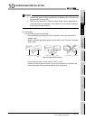
Terminal block
Solderless terminals
with insulation sleeves