


5
POWER SUPPLY MODULE
5.1 Specifications
5 - 2
1
OVERVIEW
2
SYSTEM
CONFIGURATION
3
GENERAL
SPECIFICATIONS
4
CPU MODULE
5
POWER SUPPLY
MODULE
6
BASE UNIT
7
BATTERY
8
CPU MODULE START-
UP PROCEDURES
POINT
*1: Overcurrent protection
The overcurrent protection function shuts off the 5 VDC circuit and stops the system if
the current flowing in the circuit exceeds the specified value.
The LED of the power supply module is turned off or lights up in dim green when
voltage is lowered. If this device is activated, switch the input power supply OFF and
eliminate the cause such as insufficient current capacity or short. Then, a few minutes
later, switch it ON to restart the system.
The initial start for the system takes place when the current value becomes normal.
*2: Overvoltage protection
The overvoltage protection function shuts off the 5 VDC circuit and stops the system if
a voltage of 5.5 VDC or above is applied to the circuit.
When this device is activated, the power supply module LED is turned OFF.
For restart of the system, turn OFF the input power supply, and then turn ON in a few
minutes. This allows the system to start up with initial start. If the system doesn't start
up and a LED indication remains off, replacement of a power supply module is
required.
*3: Allowable momentary power failure period
• An instantaneous power failure lasting less than 20ms will cause AC down to be
detected, but operation will continue.
• An instantaneous power failure lasting in excess of 20ms may cause the
operation to continue or initial start to take place depending on the power supply
load.
*4: Inrush current
When power is switched on again immediately (within 5 seconds) after power-off, an
inrush current of more than the specified value (2ms or less) may flow. Reapply power
5 or more seconds after power-off. When selecting a fuse and breaker in the external
circuit, take account of the blowout, detection characteristics and above matters.
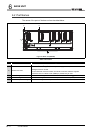
Table5.1 Power supply module specifications (Continue)
Item
Performance Specifications
QS061P-A1 QS061P-A2
Contact output part
Application
ERR. contact ( Section 5.3)
Rated switching
voltage/current
24VDC, 0.5A
Min. switching load 5VDC, 1mA
Response time
OFF ON: 10ms or less, ON OFF: 12ms or less
Life
Mechanical : 20 million times or more
Electrical : Rated switching voltage/current load: 100 thousand times or more
Surge suppressor No
Fuse No
Terminal screw size M3.5
Applicable wire size
0.75 to 2mm
2
Applicable solderless terminal RAV1.25 to 3.5, RAV2 to 3.5 (0.8mm or less thick)
Applicable tightening torque 0.66 to 0.89N•m
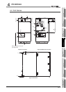
External
dimensions
H 98mm (3.86 inch)
W 55.2mm (2.17 inch)
D 115mm (4.53 inch)
Weight 0.40kg