


12
TROUBLESHOOTING
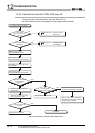
12.2 Troubleshooting Flowchart
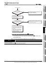
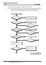
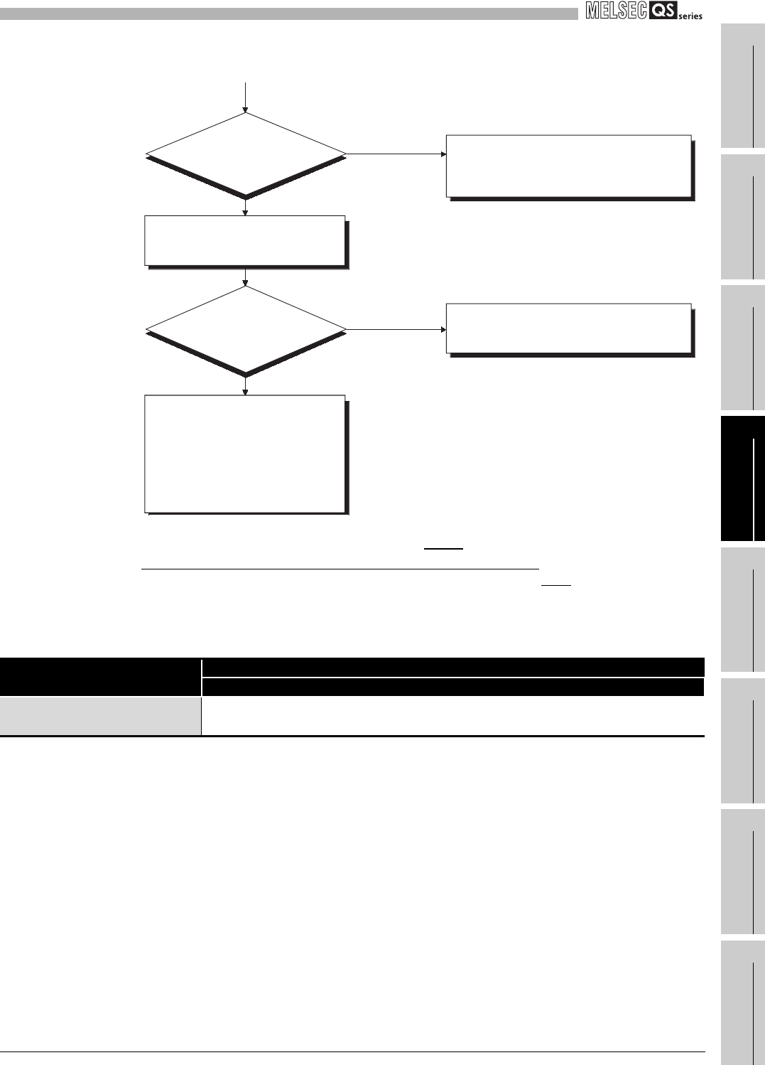
12.2.2 Flowchart for when the ERR terminal (negative logic) is off (opened)
12 - 4
9
EMC AND LOW
VOLTAGE
DIRECTIVES
10
LOADING AND
INSTALLATION
11
MAINTENANCE AND
INSPECTION
12
TROUBLESHOOTING APPENDICES INDEX
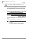
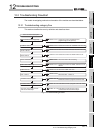
Errors that can be detected by the ERR. terminal
The following shows the errors that can be detected by the ERR. terminal of the
power supply module.
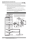
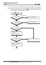
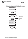
Figure 12.2 Flowchart for when the ERR terminal turns off
Table12.1 Errors that can be detected by the ERR terminal of a power supply module
Base unit
CPU module
QS001CPU
Main base unit (QS034B)
AC power not input, power supply module fuse blown and CPU module stop error
(including reset) can be detected.
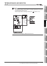
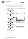
Check the sum of internal current
consumptions of the modules that
comprise the system.
Hardware error of a module other than
the power supply module and base unit
Install modules to the base unit one by
one and execute operation checks in
due order.
For the module that does not operate,
please consult your local Mitsubishi
representative, explaining a detailed
description of the problem.
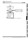
Off
Reexamine the system configuration to make the
total current less than the rated current consumption
of one power supply module.
On
The base unit that includes the corresponding
power supply module is faulty.
(Change it for a normal base unit.)
Yes
No
Does the total
current exceed the rated
current consumption of one power
supply module?
How is the "POWER"
LED of the power supply
module?
(From previous page)