


10
LOADING AND INSTALLATION
10.2 Module Installation
10.2.3 Installation and removal of module
10 - 15
9
EMC AND LOW
VOLTAGE
DIRECTIVES
10
LOADING AND
INSTALLATION
11
MAINTENANCE AND
INSPECTION
12
TROUBLESHOOTING APPENDICES INDEX
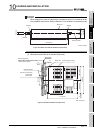
10.2.3 Installation and removal of module
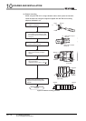
This section explains how to install and remove a power supply, CPU, intelligent function
or another module to and from the base unit.
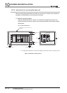
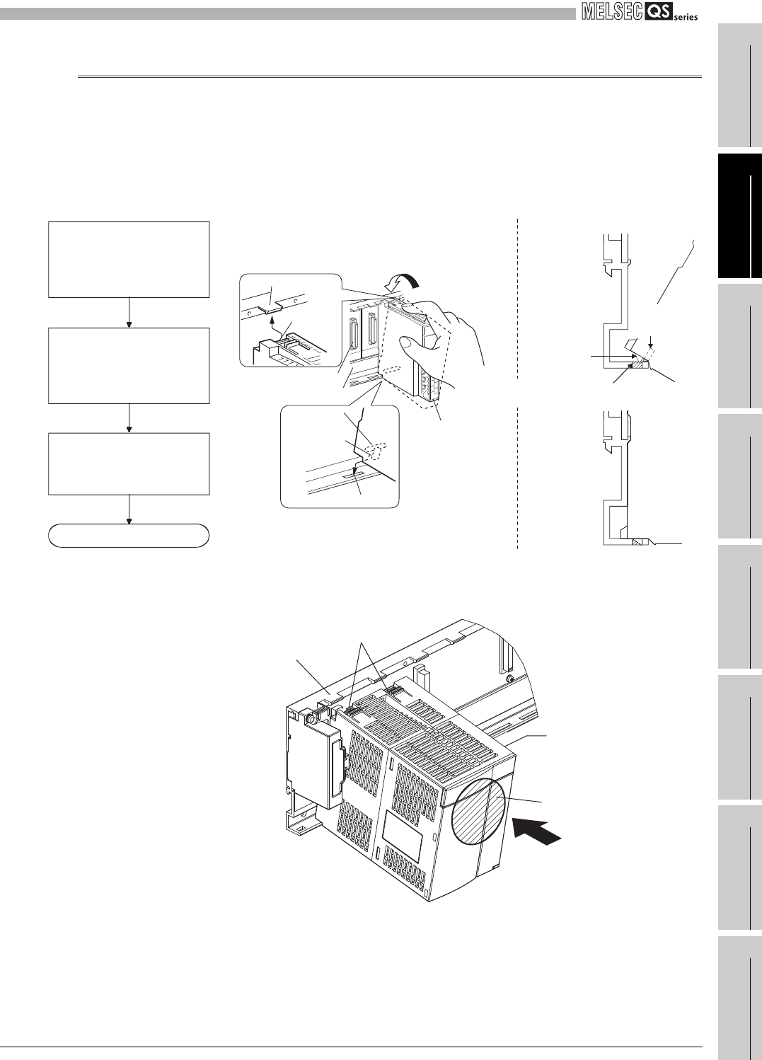
(1) Installation and removal of the module from the QS034B
(a) Installation of module on the QS034B
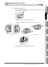
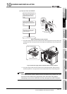
* 1: The power supply module and CPU module has two module fixing latches. Insert the two module
fixing latches on the right and left into the module fixing holes so that they are not misaligned.
* 2: The power supply module and CPU module has two module fixing hooks on its top. Push the
center top of the power supply module and CPU module and mount the module so that the two
module fixing hooks on the right and left are securely engaged with the base unit hooks.
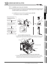
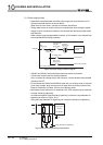
Figure 10.17 Module mounting procedure
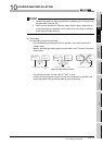
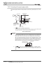
Figure 10.18 Mounting the power supply module and CPU module
Module fixing hole
Module
fixing latch
Base unit
Module loading
lever
Check that the module is
inserted in the base unit
securely and then fix it with the
module fixing screws.
Completed
Securely insert the module
fixing latch(*1) into the module
fixing hole so that the latch is
not misaligned.
Using the module fixing hole as
a fulcrum, push the module in
the direction of arrow to mount
it into the base unit.
Module
Unit fixing
hook (*2)
Base unit
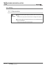
Module fixing hole
Module loading
lever
Module fixing
latch (*1)
Base unit
Module connector
Base unit hook
Module fixing hook
Power supply module
Push
Center top