


10 - 6
10.2 Module Installation
10.2.1 Installation precautions
10
LOADING AND INSTALLATION
This section gives instructions for handling the CPU, and power supply modules, base unit
and so on.
• Do not drop the module case and main module or subject them to strong impact.
• Do not remove modules' printed circuit boards from the enclosure in order to
avoid failures in operation.
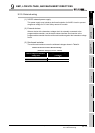
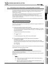
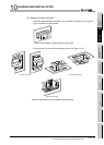
• Tighten the screws such as module fixing screws within the following ranges.
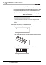
* 1 The module can be easily fixed onto the base unit using the hook at the top of the module.
However, it is recommended to secure the module with the module fixing screw if the module is
subject to significant vibration.
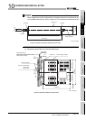
• Be sure to install a power supply module in the power supply installation slot of
QS034B.
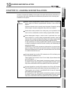
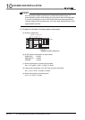
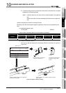
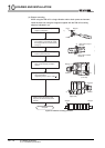
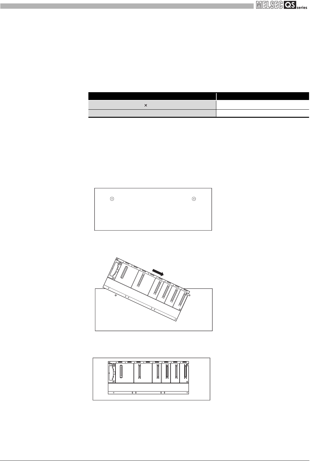
Install a base unit (by screwing) in the following procedure.
1) Fit the two base unit top mounting screws into the panel.
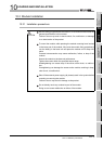
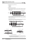
2) Place the right-hand side notch of the base unit onto the right-hand side screw.
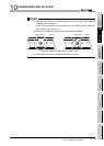
3) Place the left-hand side pear-shaped hole onto the left-hand side screw.
Table10.1 Tightening torque range
Location of Screw Tightening Torque Range
Module fixing screw (M3 12 screw)
*1
0.36 to 0.48N•m
Power supply module terminal screw (M3.5 screw) 0.66 to 0.89N•m
Figure 10.2 Install a base unit
Figure 10.3 Install a base unit
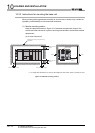
Figure 10.4 Install a base unit
Panel
Panel
Panel