


2
SYSTEM CONFIGURATION
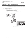
2.1 System Configuration
2 - 2
1
OVERVIEW
2
SYSTEM
CONFIGURATION
3
GENERAL
SPECIFICATIONS
4
CPU MODULE
5
POWER SUPPLY
MODULE
6
BASE UNIT
7
BATTERY
8
CPU MODULE START-
UP PROCEDURES
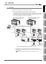
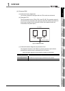
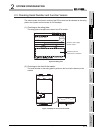
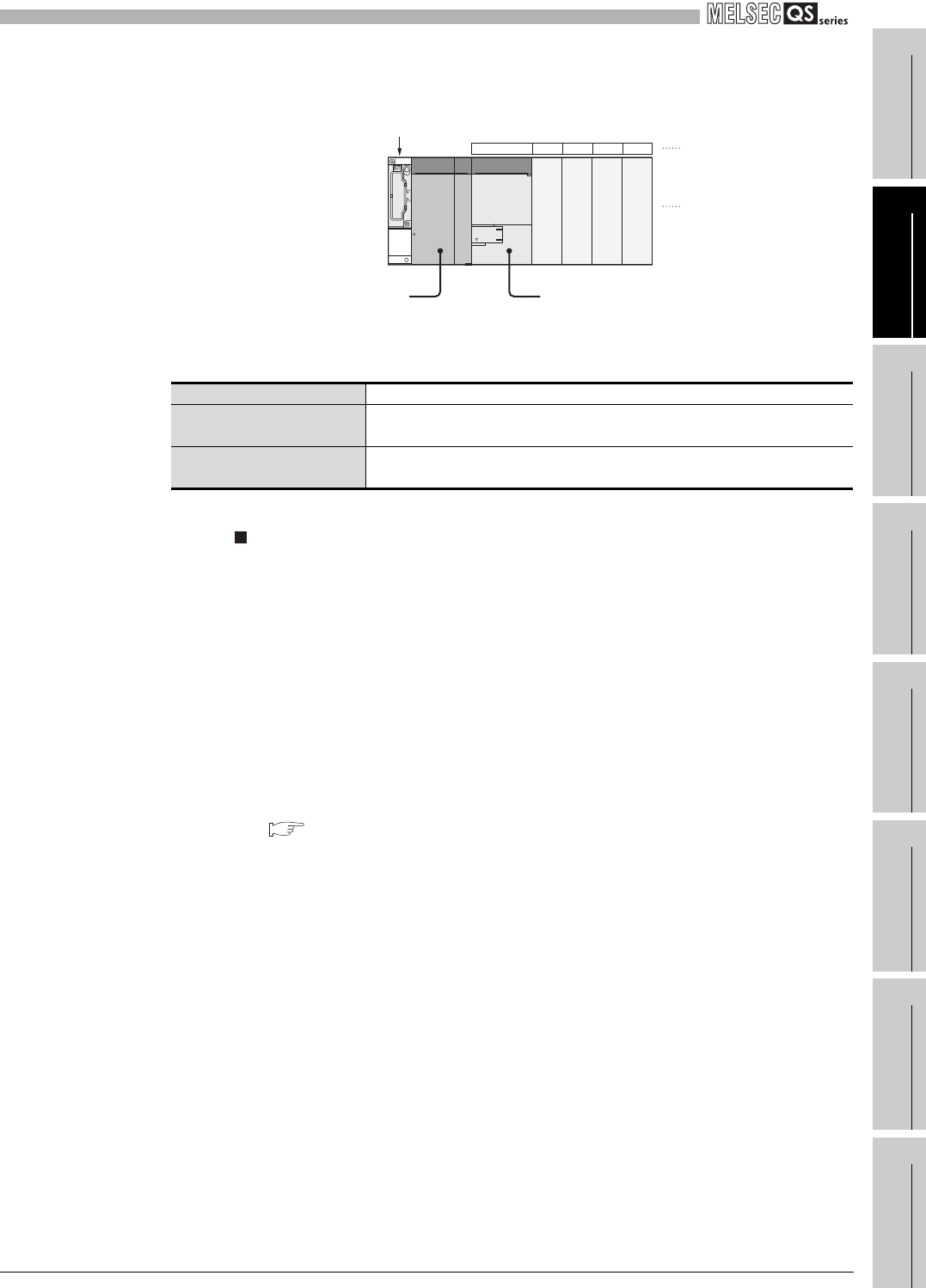
(2) System configuration overview
Precautions
• The extension base unit cannot be connected.
• The multiple CPU system cannot be configured.
• The modules which can be mounted on the I/O slot are the intelligent function
module and blank cover only.
If a module other than the ones mentioned above is mounted, "MODULE
LAYOUT ERROR" (error code: 2125) is detected.
Note, however, that a "MODULE LAYOUT ERROR" is not detected for the
slot where "Empty" has been set in the I/O assignment setting of PLC
parameter.
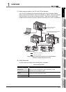
• Bus connection for the GOT is not available. For the GOT connection, refer to
the following.
GOT1000 Series Connection Manual (Mitsubishi Products)
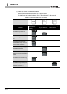
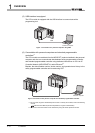
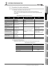
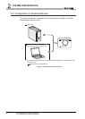
Figure 2.2 System configuration
Table2.1 Base unit and power supply module applicable to system configuration
Base unit model name QS034B
Maximum number of
mountable modules
4 modules
Power supply module model
name
QS061P-A1, QS061P-A2
00 to 0F
10 to 1F
20 to 2F
30 to 3F
CPU 0 1 2 3
CPU modulePower supply module
Base unit (QS034B)
I/O number
Slot numbe
r