


Index - 1
INDEX
[0] to [9]
5VDC internal current consumption . . . . . . . . 4-2,6-1
[A]
Allowable instantaneous power failure period . . . 4-2
Annunciator [F] . . . . . . . . . . . . . . . . . . . . . . . . . . . 4-2
[B]
Base unit
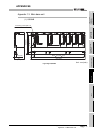
External dimensions . . . . . . . . . . . . . . . . . . . App-3
Installation and removal of module . . . . . . . . 10-15
Mounting dimensions . . . . . . . . . . . . . . . . . . 10-12
Mounting orientation . . . . . . . . . . . . . . . . . . . 10-13
Mounting position . . . . . . . . . . . . . . . . . . . . . 10-12
Parts names . . . . . . . . . . . . . . . . . . . . . . . . . . . 6-2
Battery
Battery. . . . . . . . . . . . . . . . . . . . . . . . . . . . . . . . 7-1
Installation. . . . . . . . . . . . . . . . . . . . . . . . . . . . . 7-2
Life . . . . . . . . . . . . . . . . . . . . . . . . . . . . . . . . . 11-6
Replacement procedure (CPU module) . . . . . 11-8
Replacement reference period . . . . . . . . . . . . 11-6
[C]
Calculating heat generation . . . . . . . . . . . . . . . . 10-3
Category II . . . . . . . . . . . . . . . . . . . . . . . . . . . . . 9-10
Constant scan. . . . . . . . . . . . . . . . . . . . . . . . . . . . 4-1
Control method . . . . . . . . . . . . . . . . . . . . . . . . . . . 4-1
Counter [C] . . . . . . . . . . . . . . . . . . . . . . . . . . . . . . 4-2
CPU module
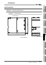
External dimensions . . . . . . . . . . . . . . . . . . . App-1
Installation and removal . . . . . . . . . . . . . . . . 10-15
Performance specifications. . . . . . . . . . . . . . . . 4-1
CPU shared memory . . . . . . . . . . . . . . . . . . . . . . 4-1
[D]
Daily inspection . . . . . . . . . . . . . . . . . . . . . . . . . 11-3
Data register [D] . . . . . . . . . . . . . . . . . . . . . . . . . . 4-2
Device
Annunciator [F] . . . . . . . . . . . . . . . . . . . . . . . . . 4-2
Counter [C] . . . . . . . . . . . . . . . . . . . . . . . . . . . . 4-2
Data register [D] . . . . . . . . . . . . . . . . . . . . . . . . 4-2
Edge relay [V] . . . . . . . . . . . . . . . . . . . . . . . . . . 4-2
Internal relay [M] . . . . . . . . . . . . . . . . . . . . . . . . 4-2
Link register [W] . . . . . . . . . . . . . . . . . . . . . . . . 4-2
Link relay [B] . . . . . . . . . . . . . . . . . . . . . . . . . . . 4-2
Link special register [SW] . . . . . . . . . . . . . . . . . 4-2
Link special relay [SB]. . . . . . . . . . . . . . . . . . . . 4-2
Special register [SD] . . . . . . . . . . . . . . . . . . . . . 4-2
Special relay [SM] . . . . . . . . . . . . . . . . . . . . . . . 4-2
Timer [T] . . . . . . . . . . . . . . . . . . . . . . . . . . . . . . 4-2
DIN rail
Applicable DIN rail. . . . . . . . . . . . . . . . . . . . . . 10-8
DIN rail mounting Adapter type. . . . . . . . . . . . . 6-1
DIN rail mounting screw intervals . . . . . . . . . . 10-8
Drive . . . . . . . . . . . . . . . . . . . . . . . . . . . . . . . . . . . 4-1
[E]
Edge relay [V] . . . . . . . . . . . . . . . . . . . . . . . . . . . . 4-2
Error codes list
Error codes returned to request source during
communication with CPU module . . . . . . . . . 12-68
External Dimensions
CPU module . . . . . . . . . . . . . . . . . . . . . . . . . App-1
Main base unit. . . . . . . . . . . . . . . . . . . . . . . . App-3
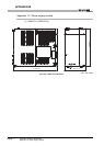
Power supply module . . . . . . . . . . . . . . . . . . App-2
[F]
Features . . . . . . . . . . . . . . . . . . . . . . . . . . . . . . . . 1-3
Ferrite core . . . . . . . . . . . . . . . . . . . . . . . . . . . . . . 9-7
[I]
I/O control mode . . . . . . . . . . . . . . . . . . . . . . . . . . 4-1
Intensive insulation . . . . . . . . . . . . . . . . . . . . . . . 9-12
Internal current consumption . . . . . . . . . . . . . 4-2,6-1
Internal relay [M] . . . . . . . . . . . . . . . . . . . . . . . . . . 4-2
[L]
LED
"BAT." LED turns on . . . . . . . . . . . . . . . . . . . 12-15
"ERR." LED of the CPU module turns on or flashes
. . . . . . . . . . . . . . . . . . . . . . . . . . . . . . . . . . . 12-11
"POWER" LED of the power supply module turns off
. . . . . . . . . . . . . . . . . . . . . . . . . . . . . . . . . . . . 12-5
"RUN" LED flashes . . . . . . . . . . . . . . . . . . . . 12-10
"RUN" LED of the CPU module turns off. . . . . 12-9
"USER" LED turns on . . . . . . . . . . . . . . . . . . 12-14
Link register [W] . . . . . . . . . . . . . . . . . . . . . . . . . . 4-2
Link relay [B] . . . . . . . . . . . . . . . . . . . . . . . . . . . . . 4-2
Link special register [SW] . . . . . . . . . . . . . . . . . . . 4-2
Link special relay [SB] . . . . . . . . . . . . . . . . . . . . . 4-2
Low voltage directive . . . . . . . . . . . . . . . . . . . 9-1,9-9
[M]
Max. number of files stored . . . . . . . . . . . . . . . . . 4-1
Memory capacity. . . . . . . . . . . . . . . . . . . . . . . . . . 4-1
Module
Installation . . . . . . . . . . . . . . . . . . . . . . . . . . . 10-15
Removal . . . . . . . . . . . . . . . . . . . . . . . . . . . . 10-17
[N]
No. of device points . . . . . . . . . . . . . . . . . . . . . . . 4-2
No. of I/O device points . . . . . . . . . . . . . . . . . . . . 4-1
Noise filter. . . . . . . . . . . . . . . . . . . . . . . . . . . . . . . 9-8