


5 - 5
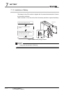
5.3 Names of Parts and Settings
5
POWER SUPPLY MODULE
POINT
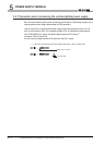
1. The QS061P-A1 is dedicated for inputting a voltage of 100 VAC.
Do not input a voltage of 200 VAC into it or trouble may occur on the
QS061P-A1.
2. Individually ground the LG and FG terminals with a ground resistance of 100
or less.
3. ERR.
terminal cannot be used as a safety output.
Connect the cable for ERR.
contact of 30m or less in length in a control panel.
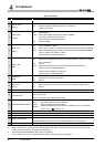
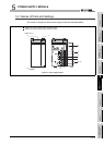
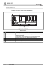
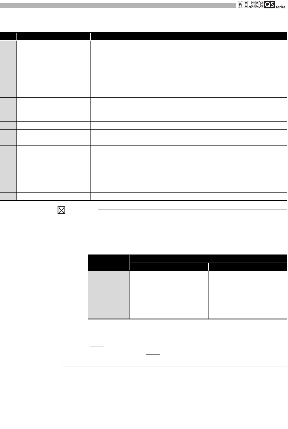
Table5.2 Part names
No. Name Application
1) "POWER" LED
On (green) : Normal (5VDC output, instantaneous power failure within 20ms)
Off : • AC power supply is ON, however, the power supply module is out of
order.
(5VDC error, overload, internal circuit failure, fuse blown)
• AC power supply is not ON.
• Power failure (including an instantaneous power failure of 20ms or
more)
2) ERR. terminal
• Turned ON when the whole system operates normally.
• Turns OFF (opens) when the AC power is not input, a stop error (including a reset)
occurs in the CPU module, or the fuse is blown.
3) FG terminal Ground terminal connected to the shielding pattern of the printed-circuit board.
4) LG terminal
Grounding for the power filter. The potential of the QS061P-A1 and QS061P-A2 ter-
minals are one-half of the input voltage.
5) Terminal screw M3.5 screw
6) Terminal cover Protective cover of the terminal block
7) Module fixing screw
Used to fix the module to the base unit.
M3 screw (Tightening torque range : 0.36 to 0.48N•m)
8) Module loading lever Used to load the module to the base unit.
9) Power input terminal Power input terminal for the QS061P-A1 and connected to a 100VAC power supply.
10) Power input terminal Power input terminal for the QS061P-A2 and connected to a 200VAC power supply.
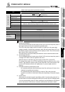
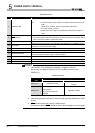
Table5.3 Precaution
Power module
type
Supply power voltage
100VAC 200VAC
QS061P-A1 Operates normally.
Power supply module causes
trouble.
QS061P-A2
Power supply module does not
cause trouble.
CPU module cannot be
operated.
Operates normally.