


10 - 8
10.2 Module Installation
10.2.1 Installation precautions
10
LOADING AND INSTALLATION
(c) Applicable DIN rail types (IEC 60715)
TH35-7.5Fe
TH35-7.5AI
TH35-15Fe
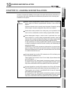
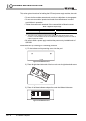
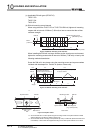
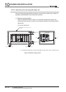
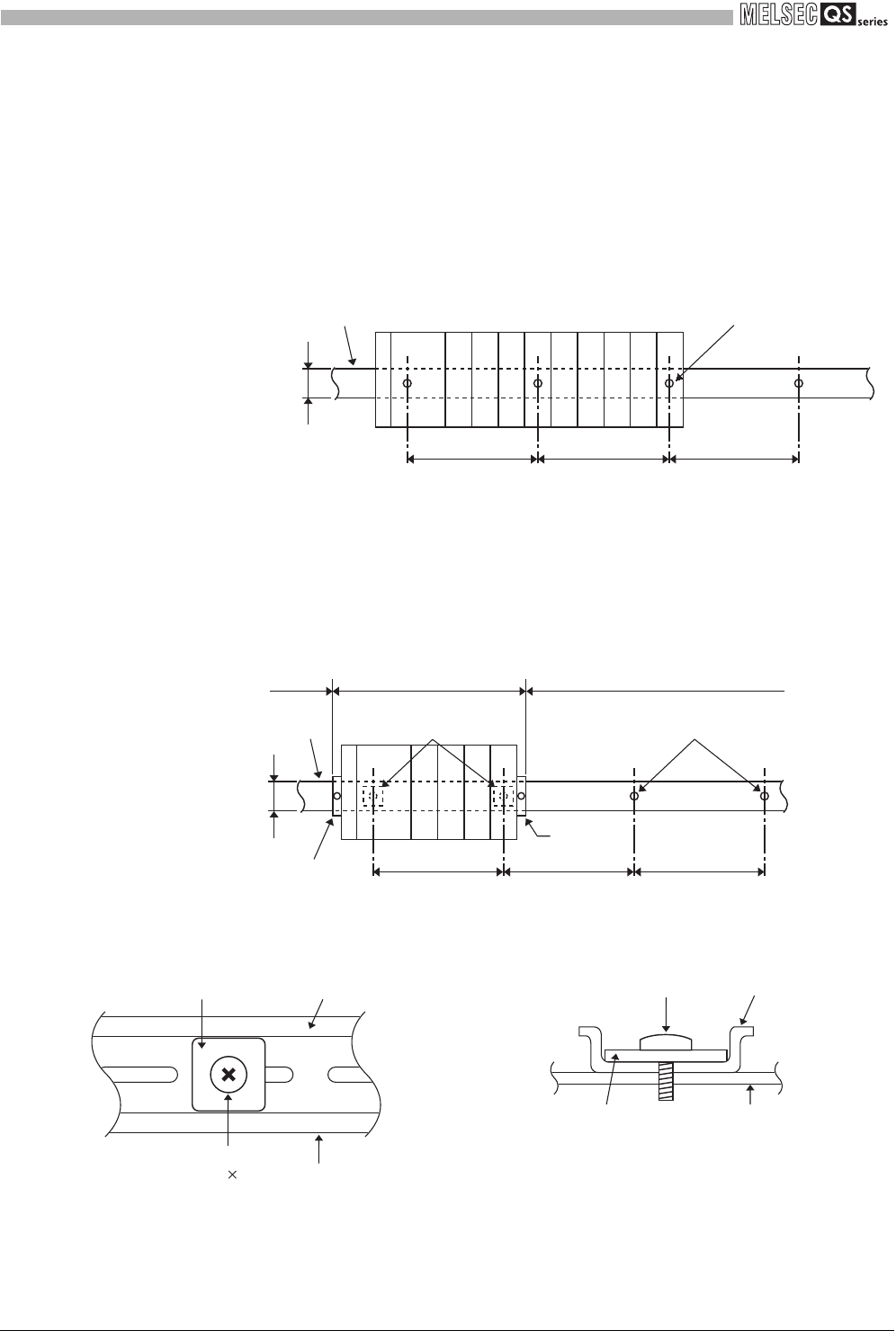
(d) DIN rail mounting screw intervals
When using either the TH35-7.5Fe or TH35-7.5Al DIN rail, tighten rail mounting
screws with an interval of 200mm (7.88 inch) or less to ensure that the rail has
sufficient strength.
When installing the DIN rail in a large vibration and/or shock prone environment,
tighten the mounting screws with an interval of 200mm (7.88 inch) or less by the
following method shown below.
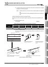
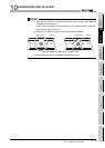
Screw the DIN rail in two places using the mounting screws and square washers
included with the adaptors in ‘Position A’ (bottom of base unit).
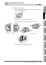
* 1
* 2: Screw the DIN rail to a control panel using the mounting screws and square washers included
with the adaptors in ‘Position A’ (bottom of base unit).
* 3: Screw the DIN rail with mounting screws(obtained by user) in ‘Position B’ (Where the base unit is
not installed). In this method the supplied mounting screws and square washers are not used.
Figure 10.6 DIN rail mounting screw intervals
Figure 10.7 DIN rail mounting screw intervals
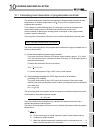
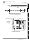
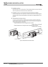
Figure 10.8 Square washer
35mm
(1.38 inch)
P=200mm (7.88 inch) or less
DIN rail
DIN rail mounting screw
(obtained by user)
PPP
DIN rail
35mm
P
P=200mm (7.88 inch) or less
PP
Stopper
Stopper
A *2B *3
B *3
Mounting screws
(included with adaptors)
Square washers necessary *1
Mounting screws (obtained by user)
No square washers
DIN rail
Mounting screws
(M5 10)
Square washer
Side view A
DIN railMounting screws
square washer
Mounting side
(e.g. Control panel)
Side view A