


4 - 4
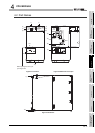
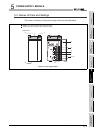
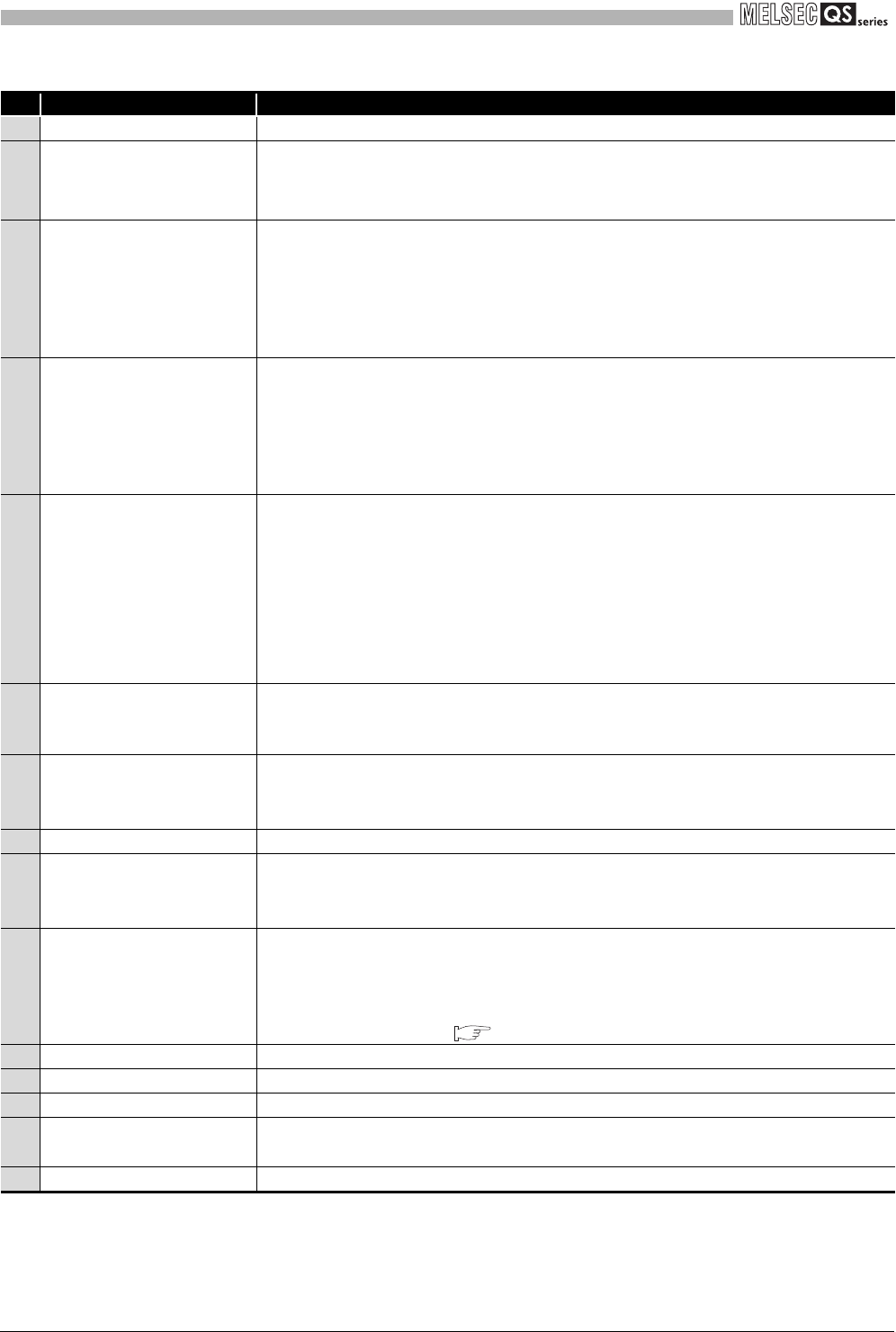
4.2 Part Names
4
CPU MODULE
*1 : Turns On during the initial processing (self-diagnostics, etc.) right after the power-on or reset cancel.
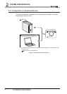
*2 : When a cable is to be connected to the USB connector at all times, clamp the cable to prevent a loose connection,
shifting, or disconnection by pulling due to carelessness.
*3 : Operate the RUN/STOP/RESET switch with your fingertips.
Do not use any tool such as a screwdriver because the switch part might be damaged.
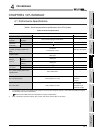
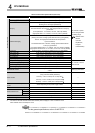
Table4.2 Part Names
No. Name Application
1) Module fixing hook Hook used to fix the module to the base unit.
2)
"ALIVE" LED
(Green)
3)
"TEST" LED
(Yellow)
Indicates the operating mode of the CPU module.
4)
"RUN" LED
(Green)
Indicates the operating status of the CPU module.
5)
"ERR." LED
(Red)
6)
"USER" LED
(Red)
7)
"BAT." LED
(Yellow)
8) Module loading lever Used to load the module to the safety base unit.
9)
USB connector
*2
Connector used to connect to the USB compatible peripheral devices.
(Connector type B)
Can be connected by the USB dedicated cable.
10)
RUN/STOP/RESET switch
*3
11) Module fixing screw Screw used to fix a module to the base unit. (M3 screw)
12) Module fixing latch Latch used to fix a module to the base unit.
13) Battery Backup battery for the power failure compensation function of program memory.
14) Battery connector pin
For connection of the battery lead wires (When shipped from the factory, the lead wires
are disconnected from the connector to prevent the battery from discharging.)
15) Serial number display Displays the serial number on the rating plate.
On :
Normal
*1
Off : When the hardware watchdog timer error is detected
("ERR." LED is On.)
On :
TEST MODE
*1
Flash : When TEST MODE is switched to SAFETY MODE
The "TEST" LED turns off after reset.
(Flash interval: On 200ms/Off 200ms)
Off : SAFETY MODE
On :
During operation in "RUN"
*1
Off : During stop in "STOP" or when the error which stops the operation is detected
Flash : When parameters/program is written during STOP and the RUN/STOP/RESET
switch is moved from "STOP" to "RUN"
(Flash interval: On 200ms/Off 200ms)
On :
When the self-diagnostics error that will not stop operation, other than a battery
error, is detected
*1
Off : Normal
Flash : When the self-diagnostics error that will stop operation is detected
(Flash interval: On 200ms/Off 200ms)
When the reset operation is performed
(Flash interval: On 60ms/Off 60ms)
On :
When the annunciator (F) turns ON
*1
Off : Normal
On :
When a battery error has occurred due to the CPU battery voltage drop
*1
Off : Normal
RUN : Executes sequence program operation.
STOP : Stops sequence program operation.
RESET :
Performs hardware reset and operation initialization when an operation
error occurs. ( Section 4.4)