


9 - 3
9.1 Requirements for Conformance to EMC Directive
9.1.2 Installation in a control panel
9
EMC, LOW VOLTAGE, AND MACHINERY DIRECTIVES
9.1.2 Installation in a control panel
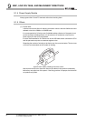
The programmable controller is open equipment and must be installed within a control
panel for use.*
This not only ensures safety but also ensures effective shielding of programmable
controller-generated electromagnetic noise.
* : Install CC-Link Safety remote stations within a control panel as well.
(1) Control panel
• Use a conductive control panel.
• When attaching the control panel's top plate or base plate, mask painting and
weld so that good surface contact can be made between the panel and plate.
• To ensure good electrical contact with the control panel, mask the paint on the
installation bolts of the inner plate in the control panel so that contact between
surfaces can be ensured over the widest possible area.
• Earth the control panel with a thick wire so that a low impedance connection to
ground can be ensured even at high frequencies.
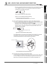
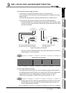
• Holes made in the control panel must be 10 cm (3.94 inch) diameter or less. If
the holes are 10 cm (3.94 inch) or larger, radio frequency noise may be emitted.
In addition, because radio waves leak through a clearance between the control
panel door and the main unit, reduce the clearance as much as practicable.
The leakage of radio waves can be suppressed by the direct application of an
EMI gasket on the paint surface.
Our tests have been carried out on a panel having the damping characteristics of
37 dB max. and 30 dB mean (measured by 3 m method with 30 to 300 MHz).
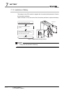
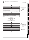
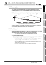
(2) Connection of power and earth wires
Earthing and power supply wires for the programmable controller system must be
connected as described below.
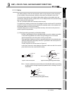
• Provide an earthing point near the power supply module. Earth the power
supply's LG and FG terminals (LG : Line Ground, FG : Frame Ground) with the
thickest and shortest wire possible. (The wire length must be 30 cm (11.81 inch)
or shorter.) The LG and FG terminals function is to pass the noise generated in
the programmable controller system to the ground, so an impedance that is as
low as possible must be ensured. As the wires are used to relieve the noise, the
wire itself carries a large noise content and thus short wiring means that the wire
is prevented from acting as an antenna.
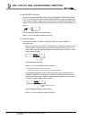
• The earth wire led from the earthing point must be twisted with the power supply
wires. By twisting with the earthing wire, noise flowing from the power supply
wires can be relieved to the earthing. However, if a filter is installed on the power
supply wires, the wires and the earthing wire may not need to be twisted.