


10
LOADING AND INSTALLATION
10.2 Module Installation
10.2.1 Installation precautions
10 - 11
9
EMC AND LOW
VOLTAGE
DIRECTIVES
10
LOADING AND
INSTALLATION
11
MAINTENANCE AND
INSPECTION
12
TROUBLESHOOTING APPENDICES INDEX
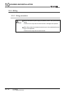
POINT
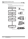
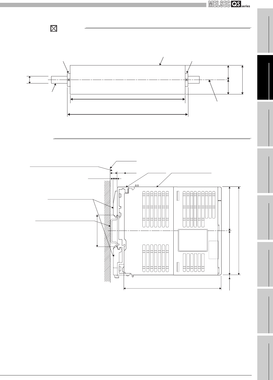
When stoppers are used, the dimension of stoppers need to be considered in the
unit installation dimensions. Refer to Section 6.1 for the base unit dimensions (W).
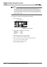
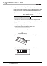
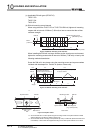
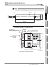
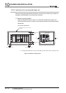
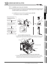
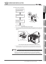
(f) Dimensions when DIN rail is attached (Side view).
Figure 10.11 Base unit external dimensions (Front view)
Figure 10.12 External dimensions (Side view)
Unit: mm (inch)
49 49
Base unit
DIN rail
W+18(0.71)
Base unit width : W
DIN rail center
35(1.38)
(1.93)
98(3.86)
(1.93)
Stopper Stopper
7.5D
3
DIN rail depth (D)
Board side
DIN rail adaptor
Base unit
115 (4.53)
Power supply module
DIN rail: TH35-7.5Fe,
TH35-7.5Al,
TH35-15Fe
TH35-7.5Fe, TH35-7.5Al:7.5 (0.30)
TH35-15Fe:15 (0.59)
(0.12)
35 (1.38)
(0.30)
98 (3.86)
(49 (1.93))(49 (1.93))
5
(0.20)
Unit: mm (inch)
5