


12 - 13
12.2 Troubleshooting Flowchart
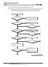
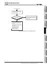
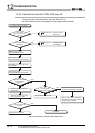
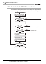
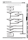
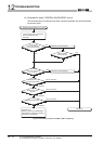
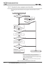
12.2.7 Flowchart for when the "ERR." LED turns on or flashes
12
TROUBLESHOOTING
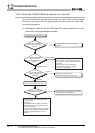
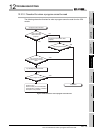
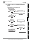
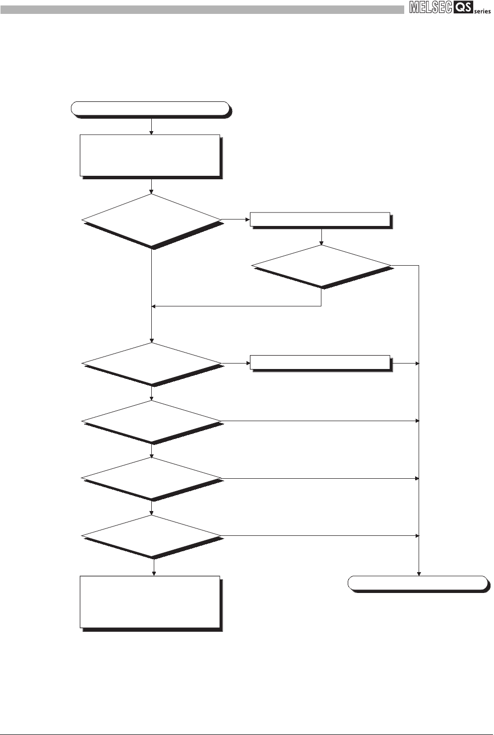
(2) Flowchart for when "CONTROL-BUS ERROR" occurs
This flowchart can be confirmed only when a specific slot/base unit can be detected
by the error code.
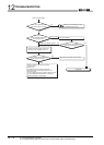
Figure 12.5 Flowchart for when the "ERR." LED is on/flashing
Error detection
Error detection
Error detection
Normal operation
Normal operation
Normal operation
The "CONTROL-BUS ERROR" has occurred.
Completed
YES
Check the slot or base unit where
the error detected by GX
Developer.
Mount the module properly.
Has the "ERR."
LED turned off?
NO
Is the module
on the corresponding
slot mounted properly?
Mount the module properly.
YES
NO
Replace the
corresponding module.
Replace the CPU
module.
Replace the base unit.
Hardware error
Please consult your local Mitsubishi
representative, explaining a detailed
description of the problem.
YES
NO
Has noise in
excess of the specified value
been generated?