


10
LOADING AND INSTALLATION
10.2 Module Installation
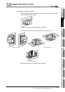
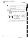
10.2.3 Installation and removal of module
10 - 17
9
EMC AND LOW
VOLTAGE
DIRECTIVES
10
LOADING AND
INSTALLATION
11
MAINTENANCE AND
INSPECTION
12
TROUBLESHOOTING APPENDICES INDEX
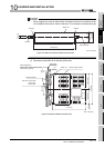
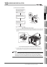
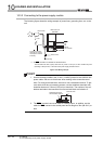
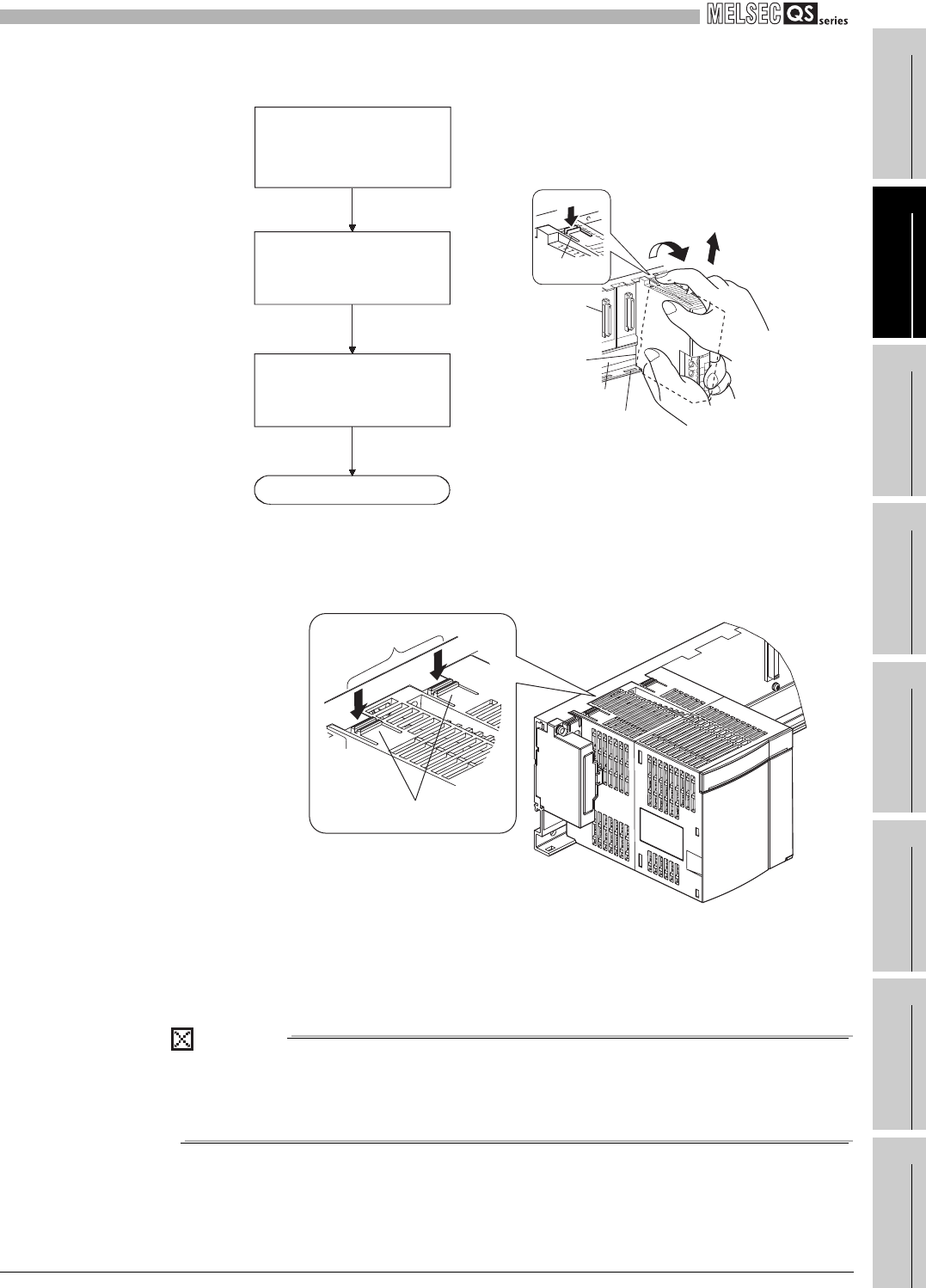
(b) Removal from the QS034B
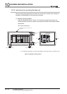
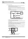
* 1: The power supply module and CPU module has two module fixing hooks on its top. Push the two
module fixing hooks on the right and left of the module top simultaneously with your fingers until
they stop.
* 2: The power supply module and CPU module has two module fixing latches. Remove the two
module fixing latches on the right and left of the module bottom from the module fixing holes.
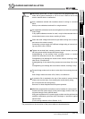
POINT
When removing the module, always remove the module fixing screw(s) first, and
then remove the module fixing projection(s) from the module fixing hole(s).
Attempting to remove the module by force may damage the module fixing latch.
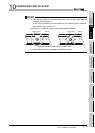
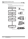
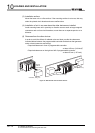
Figure 10.19 Module removal procedure
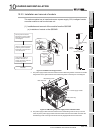
Figure 10.20 Power supply module and CPU module removal procedure
Completed
Pull the module based on the
supporting point of module bottom
while pressing the module fixing
hook .
While lifting the module, take the
module fixing latch(*2) off the
module fixing hole.
Remove the module fixing screw.
Then support the module with both
hands
and securely press the
module fixing hook*1 with your
finger.
Module
Module
connector
Module fixing hole
Base unit
Push
Module fixing
hook *1
Lifting
Push simultaneously
Module fixing hooks