


10 - 12
10.2 Module Installation
10.2.2 Instructions for mounting the base unit
10
LOADING AND INSTALLATION
10.2.2 Instructions for mounting the base unit
When mounting the programmable controller to an enclosure or similar, fully consider its
operability, maintainability and environmental resistance.
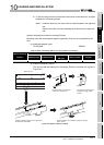
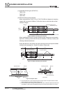
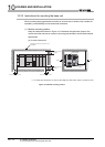
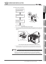
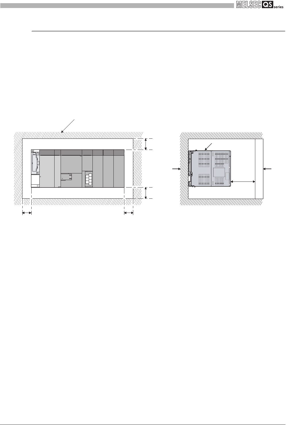
(1) Module mounting position
Keep the clearances shown in Figure 10.13 between the top/bottom faces of the
module and other structures or parts to ensure good ventilation and facilitate module
replacement.
(a) In case of base unit
* 1: For wiring duct with 50mm (1.97 inch) or less height. For other cases, 40mm (1.58 inch) or more.
Figure 10.13 Module mounting position
Indicates the panel top, wiring duct or any
part position.
30mm(1.18 inch)
or more
Panel
5mm (0.20 inch) or more
5mm (0.20 inch) or more
20mm
(0.79 inch)
or more
Door
Programmable
logic controller
30mm(1.18 inch)
or more
*1