


6 - 2
6.2 Part Names
6
BASE UNIT
6.2 Part Names
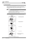
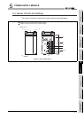
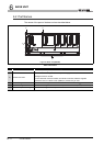
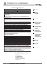
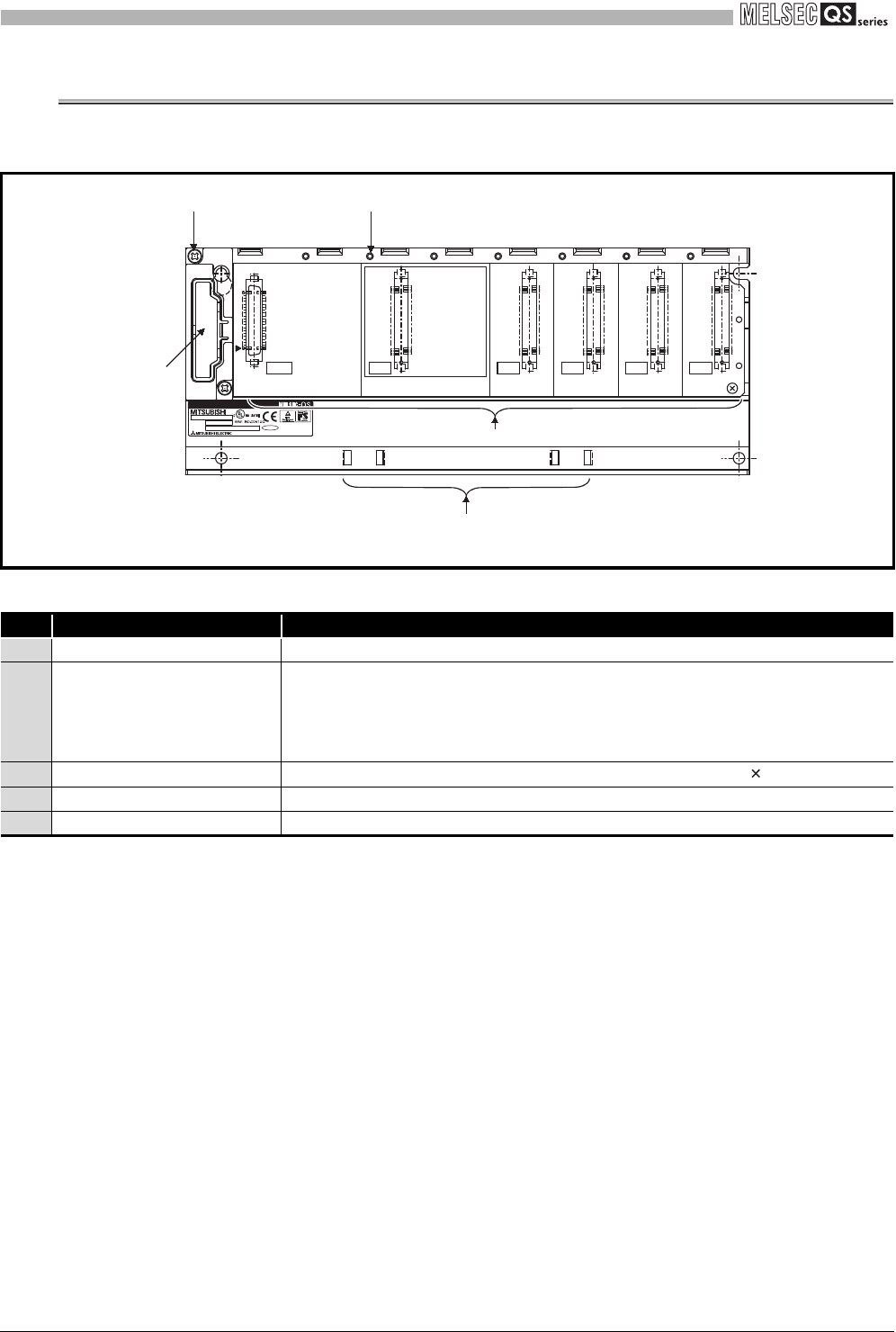
The names of the parts of the base unit are described below.
Figure 6.1 Base unit (QS034B)
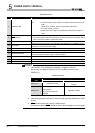
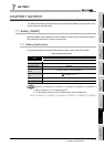
Table6.2 Part Names
No. Name Application
1) Base cover Cover for protecting the printed-circuit board of the base unit
2) Module connector
Connector for installing the QS series power supply module, CPU module and
intelligent function module.
For the reserved connector where no module is mounted, attach a supplied
connector cover or a blank cover (QG60) to prevent entry of dust.
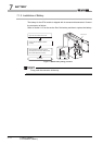
3) Module fixing screw hole
Screw hole for fixing the module to the base unit. Screw size: M3 12
4) Base mounting hole Hole for mounting this base unit onto the panel of the control panel (for M4 screw)
5) DIN rail adapter mounting hole Hole for mounting DIN rail adapter
OUT
I/O3I/O2I/O1I/O0CPU
POWER
b1
a1
BD992C202H01
SERIAL
MODEL
MADE IN JAPAN
PASSED
1)
4) 3)
2)
5)