


10 - 10
10.2 Module Installation
10.2.1 Installation precautions
10
LOADING AND INSTALLATION
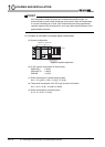
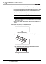
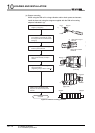
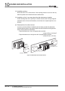
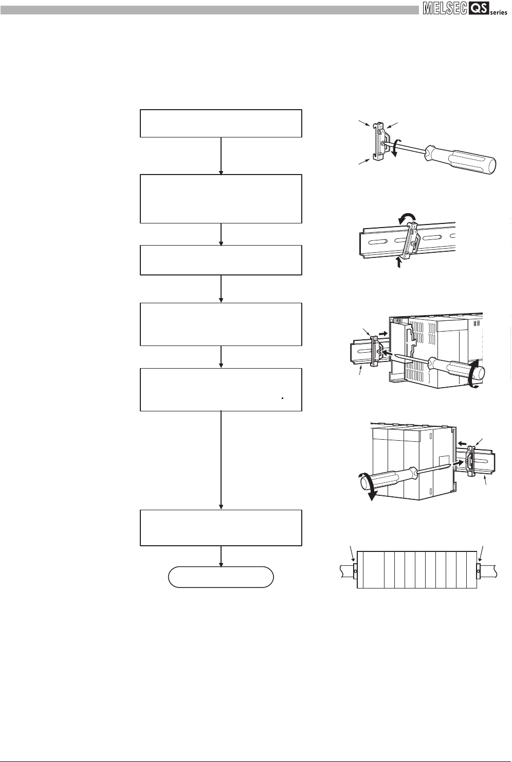
(e) Stopper mounting
When using the DIN rail in a large vibration and/or shock prone environment,
install the base unit using the stoppers supplied with the DIN rail mounting
adaptors indicated in (a).
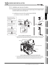
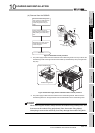
Figure 10.10 Fixture mounting procedure
4)
5)
Stopper
(Left side)
4)
5)
Stopper
(Right side)
2)
3)
1)
Stopper
Hook
Hook
Stopper Stopper
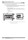
Hitch hook to top of
DIN rail
Hitch hook to bottom
of DIN rail
DIN rail
DIN rail
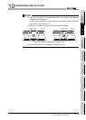
Complete
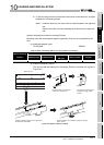
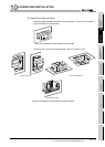
1)
2)
3)
4)
5)
Loosen the screw at the top of the
stopper. (2 stoppers)
Hitch the lower hook of the stopper
to the bottom of the DIN rail. Install
the stopper with the arrowhead side
facing up.
Hitch the upper hook of the stopper
to the top of the DIN rail.
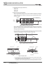
Slide the stopper to the end of the
base unit so that they are fully in
contact.
Tighten the screw of the stopper
with a screwdriver.
(Tightening torque 1.00 to 1.35N m)
Make sure that the left and right
stoppers are fixed securely to the
DIN rail.