


10
LOADING AND INSTALLATION
10.2 Module Installation
10.2.1 Installation precautions
10 - 7
9
EMC AND LOW
VOLTAGE
DIRECTIVES
10
LOADING AND
INSTALLATION
11
MAINTENANCE AND
INSPECTION
12
TROUBLESHOOTING APPENDICES INDEX
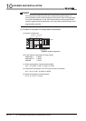
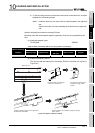
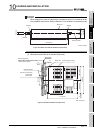
4) Fit the mounting screws into the holes at the bottom of the base unit, and then
retighten the 4 mounting screws.
Note1 : Install the base unit to a panel, with no module loaded in the right-end
slot.
Remove the base unit after unloading the module from the right-end
slot.
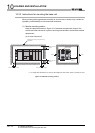
Note the following points when mounting a DIN rail.
Mounting a DIN rail needs special adaptors (optional), which are to be prepared by the
user.
(a) Applicable adaptor types
For QS034B : Q6DIN2
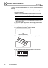
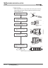
(b) Adaptor installation method
The way to install the adaptors for mounting a DIN rail to the base unit is given in
Figure 10.5.
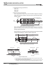
Table10.2 Parts included with DIN rail mounting adaptors included parts
DIN rail mounting
adaptors
Quantity of included parts
Adaptor(Large) Adaptor(small)
Mounting screw
(M5 10)
Square washer Stopper
Q6DIN2 23222
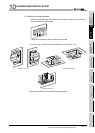
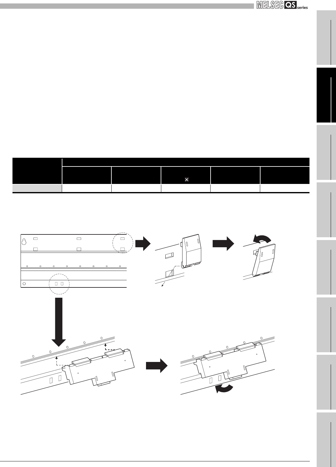
Figure 10.5 Adaptor installation method
Base unit rear
Place the hook of the adaptor
(small) in the lower hole.
Push the top of the adaptor
(small) far enough until it
"clicks".
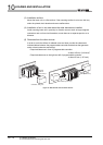
Insert the adaptor (large) into the grooves of
the base unit from below.
Push the bottom of the adaptor (large) far enough
until it "clicks".