


13
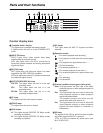
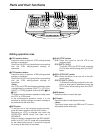
Panel switch area
7
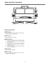
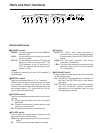
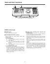
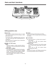
ANALOG AUDIO IN switch
Used to set the allocation of the audio signals to the
4 analog audio input connectors (on the rear panel).
V1-V2 (2ch)
:Of the 4 inputs, the two on the VTR1
side are supplied to the VTR1’s input
connectors, and the two on the VTR2
side are supplied to the VTR2’s input
connectors.
V1 (4ch)
: The 4 inputs are allocated to the 4
channels of VTR1.
V2 (4ch)
: The 4 inputs are allocated to the 4
channels of VTR2.
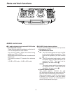
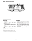
8
ANALOG AUDIO OUT switch
Used to set the allocation of the audio signals to the
4 analog audio output connectors (on the rear
panel).
V1-V2 (2ch)
:Of the 4 outputs, two on the VTR1 side
are supplied to the VTR1’s output
connectors, and two on the VTR2 side
are supplied to the VTR2’s output
connectors.
V1 (4ch)
: The 4 outputs are allocated to the 4
channels of VTR1.
V2 (4ch)
: The 4 outputs are allocated to the 4
channels of VTR2.
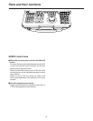
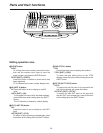
9
OPERATION MODE switch
INT
: In this mode, editing from VTR1 to VTR2 is
accomplished using the internal connections.
VTR1 recording is prohibited.
EXT
: In this mode, editing from VTR1 to VTR2 is
accomplished using the external analog
connections.
VTR1 recording is prohibited.
SEPARATE
:
In this mode, VTR1 and VTR2 are operated
independently.
:
V2 VIDEO input selector switch
Used to select the video input of VTR2 when the
OPERATION MODE switch is at the EXT or
SEPARATE position.
SDI
: Serial digital video signals are input.
ANALOG
:Analog video signals are input.
Parts and their functions
CONTROL
REMOTE
LOCAL
EXT VTR
PREROLL SYNCHRO
7
5
3
CF
ON
OFF
REGEN
R-RUN
F-RUN
MODE
REC INHIBIT
TC
VTR 1
TAPE
EE
ON
OFF
REGEN
R-RUN
F-RUN
MODE
REC INHIBIT
TC
VTR 2
TAPE
EE
ON
OFF
ANALOG
OPERATION
MODE
EDIT
V2
VIDEO IN
SDI
ANALOG
SEPARATE
EXT
AUDIO
IN
V1-V2
V1
V2
OUT
2
CH
4
CH
2
CH
4
CH
INT
7 8 9 :