


18
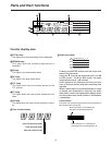
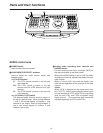
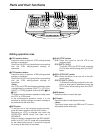
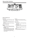
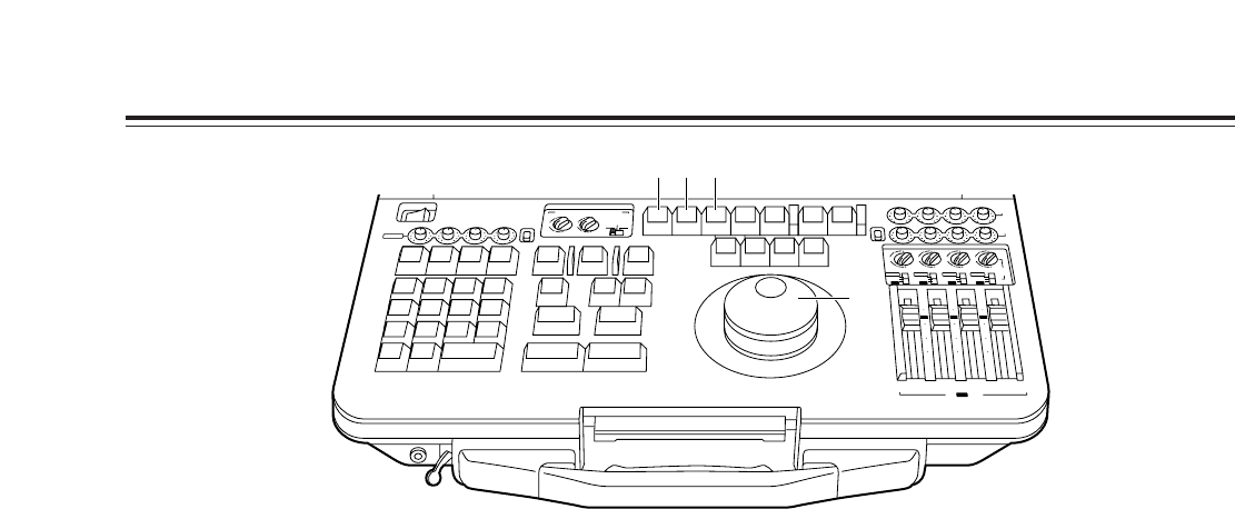
Editing operation area
8
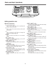
Search dial
This is used to control the tape travel. It is also
used when edit points are to be located or when
playing back tapes.
The shuttle mode is established when the dial is
“out” (up), and the jog mode is established when it
is pushed in.
Each time the dial is pressed, the unit alternates
between these two modes.
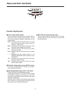
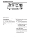
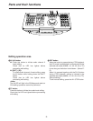
9
ASMBL (1ST EDIT) button
ASMBL
:
Press this button to initiate assemble editing.
Check that its LED has lighted before proceeding
with editing.
1ST EDIT ([SHIFT] + [ASMBL])
:
The editing tape must have black burst signals,
time codes or CTL signals recorded on it ahead
of time. To initiate first editing, press the ASMBL
button while holding down the SHIFT button.
For further details, refer to page 53 (“Preparing
tapes for editing”).
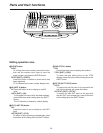
:
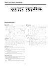
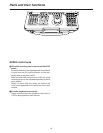
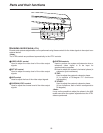
V button
Press this button to initiate video insert editing.
Check that its LED has lighted before proceeding
with editing.
;
A1 (A3) button
A1
: Press this button to initiate audio channel 1
insert editing.
Check that its LED has lighted before
proceeding with editing.
A3 ([SHIFT] + [A1])
:
To initiate audio channel 3 insert editing, press
the A1 button while holding down the SHIFT
button.
Check that its LED has lighted before
proceeding with editing.
<Note>
The A3 LED will light in the 25 Mbps mode also but
CH3 editing operations cannot be performed.
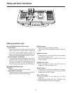
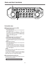
Parts and their functions
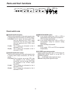
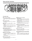
AUDIO MONITOR SELECT
LR
CH 1
4
1
3
MIX
ANALOG
MIX
2
UNI
V2
PB
SDI
REC
VAR
CH 2 CH 3 CH 4
CH 3 4
4
(V1·2)
V1 V2
1
3
MIX
MIX
2
4
1
3
MIX
MIX
A
S
M
B
L
VA
1
A
2
1
S
T
E
D
IT
P
R
E
V
IE
W
V
T
R
2
V
T
R
1
S
P
L
IT
M
A
R
K
O
U
T
M
A
R
K
IN
S
H
IF
T
E
N
T
E
R
A
L
L
S
T
O
P
R
E
V
IE
W
A
U
T
O
E
D
IT
M
U
L
T
I
G
O
T
O
G
O
T
O
O
U
T
D
U
R
T
O
T
A
L
O
U
T
L
A
S
T
E
D
IN
L
A
S
T
X
E
V
E
N
T
78
9
456
1
2
0C
3
~
-
+
D
E
L
E
T
E
S
E
T
U
P
F
/T
C
D
IA
G
L
IS
T
C
O
R
C
T
B
S
T
R
A
C
K
D
U
M
P
L
O
A
D
F
S
D
IS
P
E
X
IT
R
E
T
U
R
N
T
S
E
T
P
L
A
Y
S
T
O
P
S
T
I
L
L
R
E
W
F
F
S
T
B
O
F
F
A
3
A
4
T
CR
E
C
E
D
IT
2
4
1
3
MIX
MIX
2
4
1
3
MIX
MIX
2
4
1
3
MIX
MIX
2
SDI
CH 1 CH 2
V2
/ V1 PB
REC
CH 3 CH 4
INT
ANALOG
SDI
10
10
20
30
00
INT
INT
ANALOG
SDI
INT
ANALOG
SDI
V2
INPUT
INT
0
10
10
20
30
00
0
10
10
20
30
00
0
CH 1
POWER
OFF
ON
UNI
VAR
CH 2 CH 3 CH 4
ANALOG
V1/V2
REC
9 : ;
8