


24
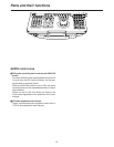
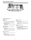
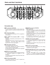
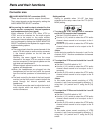
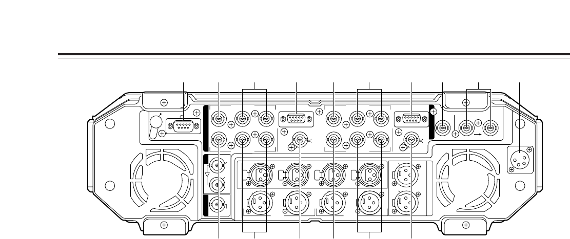
Connector area
1
EDL connector (D-SUB 9P)
Connect a personal computer or other external unit
to this connector to upload and download the edit
data.
2
TC IN connector (BNC)
The external time code signal (LTC) is supplied to
this connector.
3
REF VIDEO IN connectors (BNC
a
2, loop-
through)
These are automatically terminated with a 75 Ω
resistance.
Supply standard analog composite signals to these
connectors. The unit’s video output will be
synchronized with the input signals.
4
DC IN connector (XLR 4P)
This is the DC power input socket.
The AJ-B95, available as an optional accessory
must be used for the power supply.
No guarantees are made when the unit is operated
by any other power supply.
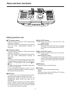
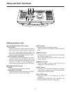
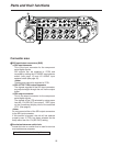
5
VIDEO/Y IN connector (BNC)
The analog composite signals or analog component
Y (luminance) signals are supplied to this
connector.
The signals are selected using setup menu item
No.670 (V IN SEL).
6
P
B
/P
R
IN connectors (BNC)
The analog component P
B
and P
R
signals are
supplied to these connectors.
7
REMOTE connector (D-SUB 9P)
(525i mode only)
This remote connector complies with the RS-422A
standard. It enables the unit to be controlled using
an external controller.
The remote connector of VTR1 is switched to the
REMOTE OUT connector by setting the CONTROL
switch to “EXT VTR”.
An externally connected VTR can then be
controlled using the unit’s VTR1 operation system.
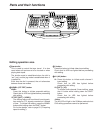
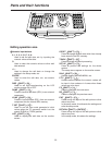
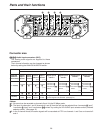
8
VIDEO/Y OUT connector (BNC)
The analog composite signals or analog component
Y (luminance) signals are output from this
connector.
The signals are selected using setup menu item
No.671 (V OUT SEL).
9
P
B
/P
R
OUT connectors (BNC)
These are the output connectors for the analog
component P
B
and P
R
signals.
:
VIDEO MONITOR OUT/TC OUT connector (BNC)
The video monitor signals are output from this
connector.
The time code signal (LTC) is output when
“TCOUT1” or “TCOUT2” has been selected as the
setup menu item No.572 (V-MON/TC OUT) setting.
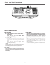
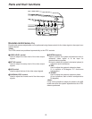
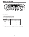
Parts and their functions
DC IN
REF INTC IN
REMOTEREMOTE
V
T
R
1
A
U
D
I
O
M
O
N
O
U
T
A
U
D
I
O
I
N
A
U
D
I
O
O
U
T
VIDEO
MON
OUT
TC
OUT
75Ω AUTO
VIDEO
MON
OUT
TC
OUT
L
CH 4
VIDEO OUT
VIDEO IN
P
B
P
B
P
R
P
R
VIDEO OUT
ACTIVE THROUGH
SDI
IN
SDI
IOUT
VIDEO IN
VIDEO/Y
VIDEO/Y
EDL
NOT USER
SERVICEABLE
VIDEO/Y
VIDEO/Y
P
B
P
B
P
R
P
R
(CH 2•4)
CH 3
(CH 1•3)
CH 4
(CH 2/4)
CH 3
(CH 1/3)
CH 2
(CH 2/4)
(V2) (V1)
CH 1
(CH 1/3)
CH 2
MIC
CH 1
R
V
T
R
2
V
2
V
1
/
V
2
1 5 7 5 7 2 4366
8 : 8 :99