


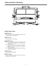
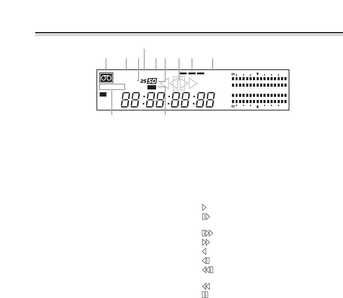
9
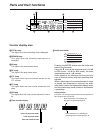
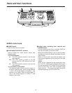
Counter display area
1
“Cassette inside” display
This lights when a cassette has been inserted.
It flashes when the unit is in the STANDBY OFF
mode.
2
INPUT SCH lamp
INPUT lights when video signals have been
supplied from an external source.
SCH also lights when the SC-H (subcarrier to
horizontal) phase matches and analog composite
signals are input.
3
REF SCH lamp
REF lights when the reference signal has been
supplied to the REF VIDEO IN connector.
SCH also lights when the SC-H phase matches and
the reference signal is input.
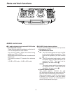
4
EDIT REC/REC/REC INH lamp
EDIT REC
: This lights when the unit is in the edit
recording mode.
REC
: This lights when the unit is in the
recording mode.
REC INH
: This lights when the unit is in the
recording inhibited mode.
5
CF lamp
This lights when the color frame is locked.
6
SERVO lamp
This lights when the servo is locked.
7
25/50 lamps
25
: This lights during DVCPRO (25 Mbps mode)
recording or playback.
50
: This lights during DVCPRO (50 Mbps mode)
recording or playback.
8
625 lamps
This lights when the 625i TV system has been
selected.
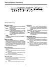
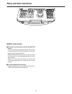
9
Operation modes
: For normal playback and recording.
: For playback at less than the normal speed
(1
a
).
: For playback at a speed faster than 1
a
.
: For fast forwarding.
: For reverse playback at 1
a
.
: For reverse playback at less than 1
a
.
: For reverse playback at a speed faster than
1
a
.
: For rewinding.
: For pause/still.
:
Channel condition lamps (green
“
blue
“
red)
Green
: This lights when the error rate of the video
playback signals or audio playback signals is
acceptable.
Blue
: This lights when the error rate of either the
video playback signals or audio playback
signals has deteriorated.
The playback picture and sound are still
normal even when this lamp is on.
Red
: This lights when the error rate of either the
video playback signals or audio playback
signals has been subject to correction or
interpolation.
;
SDI lamp
The signals of the VTR for which this lamp is lighted
are output from the SDI OUT connector.
VTR1 or VTR2 is selected by setup menu item
No.174 (SDI OUT).
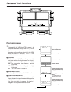
Parts and their functions
CTL
TC
UB
3
CH
4
CH
CH
2
CH
1
-
30
dB
20 16 12 8 4 0
INPUT SCH
REF SCH
SDI
DF
SERVOCF
TOTAL
REMAIN
EDIT REC
INH
525
W
625
-
30
dB
20 16 12 8 4 0
1 2 3
5
4 8
6 7 ;9 :