


15
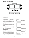
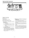
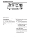
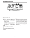
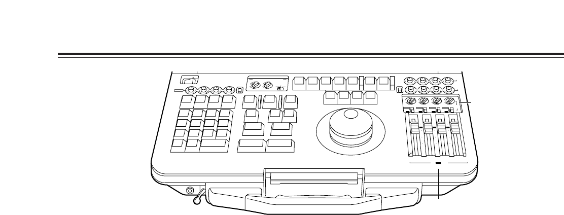
AUDIO control area
4
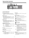
V1 audio playback level controls/V2 INT audio
recording level controls
These controls enable the playback audio level of
VTR1 to be adjusted for each channel.
They are also used to adjust the volume during
editing from VTR1 to VTR2.
Slide controls are used to make for fine and smooth
adjustments.
The position marked “0” denotes the reference
level.
(–20 dB for 525i mode; –18 dB for 625i mode)
5
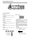
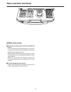
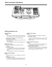
V2 AUDIO input selector switches
Used to select the sound which is to be input to the
audio channels of VTR2.
O
INT/SDI/ANALOG switch
INT
: The VTR1 audio signals are input to VTR2
by the internal digital connections. Their
level can be adjusted by the level controls
4
.
SDI
: The SDI embedded audio signals, which
have been input to the SDI connector, are
supplied to VTR2. Their level can be
adjusted by the level controls
6
.
ANALOG
:
The analog signals which have been input
are supplied to VTR2. Their level can be
adjusted by the level controls
3
.
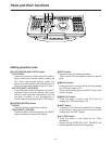
O
Channel selector switches
The audio signals selected by the
INT/SDI/ANALOG switch are input to the VTR2
channels which are selected by these switches.
When mixing between 1 and 2, the mixed signals
of channel 1 and channel 2 are input; when
mixing between 3 and 4, the mixed signals of
channel 3 and channel 4 are input.
Parts and their functions
AUDIO MONITOR SELECT
LR
CH 1
4
1
3
MIX
ANALOG
MIX
2
UNI
V2
PB
SDI
REC
VAR
CH 2 CH 3 CH 4
CH 3 4
4
(V1·2)
V1 V2
1
3
MIX
MIX
2
4
1
3
MIX
MIX
A
S
M
B
L
V
A
1
A
2
1
S
T
E
D
IT
P
R
E
V
IE
W
V
T
R
2
V
T
R
1
S
P
L
I
T
M
A
R
K
O
U
T
M
A
R
K
IN
S
H
I
F
T
E
N
T
E
R
A
L
L
S
T
O
P
R
E
V
IE
W
A
U
T
O
E
D
IT
M
U
L
T
I
G
O
T
O
G
O
T
O
O
U
T
D
U
R
T
O
T
A
L
O
U
T
L
A
S
T
E
D
IN
L
A
S
T
X
E
V
E
N
T
7
89
456
1
2
0C
3
~
-
+
D
E
L
E
T
E
S
E
T
U
P
F
/T
C
D
IA
G
L
IS
T
C
O
R
C
T
B
S
T
R
A
C
K
D
U
M
P
L
O
A
D
F
S
D
IS
P
E
X
IT
R
E
T
U
R
N
T
S
E
T
P
L
A
Y
S
T
O
P
S
T
IL
L
R
E
W
F
F
S
T
B
O
F
F
A
3A
4
T
CR
E
C
E
D
IT
2
4
1
3
MIX
MIX
2
4
1
3
MIX
MIX
2
4
1
3
MIX
MIX
2
SDI
CH 1 CH 2
V2
/ V1 PB
REC
CH 3 CH 4
INT
ANALOG
SDI
10
10
20
30
00
INT
INT
ANALOG
SDI
INT
ANALOG
SDI
V2
INPUT
INT
0
10
10
20
30
00
0
10
10
20
30
00
0
CH 1
POWER
OFF
ON
UNI
VAR
CH 2 CH 3 CH 4
ANALOG
V1/V2
REC
4
5