


25
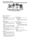
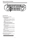
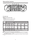
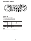
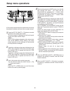
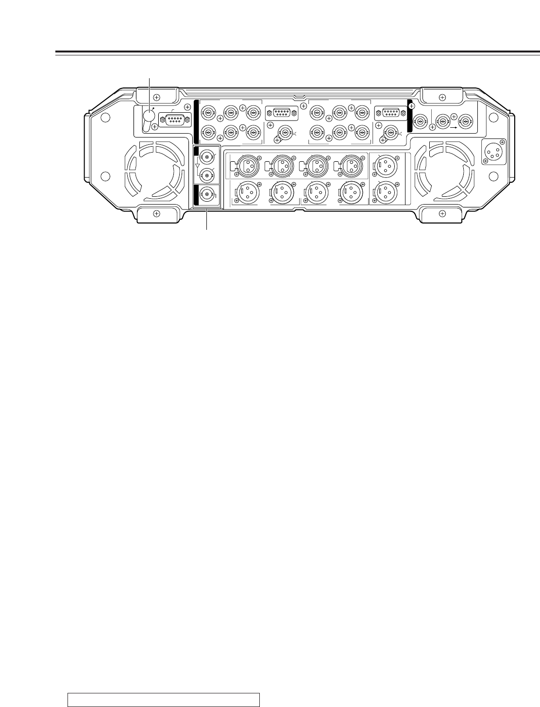
Connector area
;
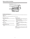
SDI input/output connectors (BNC)
O
SDI input connector
This is the input connector for the component
serial digital signals.
SDI signals can be supplied to VTR2 and
recorded by setting the V2 VIDEO input selector
switch (see page 13) and V2 AUDIO input
selector switch (see page 15).
<Note>
These signals cannot be supplied to VTR1.
O
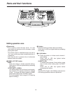
SDI ACTIVE THRU output connector
The signals supplied to the SDI input connector
are output straight through the unit via the output
buffer.
O
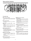
SDI output connector
This is the output connector for the component
serial digital signals.
The signals of the VTR selected by setup menu
item No.174 (SDI OUT) are output. “SDI” lights
on the fluorescent display tube of the selected
VTR. (See page 9)
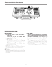
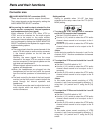
<Note>
Do not connect either of the SDI output connectors
to the SDI input connector.
If this caution is ignored, the unit will not operate
properly even if VTR1 has been selected as the
setup menu item No.174 (SDI OUT) setting.
<
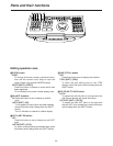
Service/maintenance switch hole
Inside this hole is a switch that is used for service
and maintenance purposes.
It should never be touched by the user.
Parts and their functions
DC IN
REF INTC IN
REMOTEREMOTE
V
T
R
1
A
U
D
I
O
M
O
N
O
U
T
A
U
D
I
O
I
N
A
U
D
I
O
O
U
T
VIDEO
MON
OUT
TC
OUT
75Ω AUTO
VIDEO
MON
OUT
TC
OUT
L
CH 4
VIDEO OUT
VIDEO IN
P
B
P
B
P
R
P
R
VIDEO OUT
ACTIVE THROUGH
SDI
IN
SDI
IOUT
VIDEO IN
VIDEO/Y
VIDEO/Y
EDL
NOT USER
SERVICEABLE
VIDEO/Y
VIDEO/Y
P
B
P
B
P
R
P
R
(CH 2•4)
CH 3
(CH 1•3)
CH 4
(CH 2/4)
CH 3
(CH 1/3)
CH 2
(CH 2/4)
(V2) (V1)
CH 1
(CH 1/3)
CH 2
MIC
CH 1
R
V
T
R
2
V
2
V
1
/
V
2
<
;