


COMSPHERE 6800 Series Network Management System
4-14 January 1997 6800-A2-GN22-30
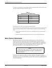
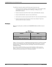
To connect a cascaded hub, you must modify a modular cable (part number 035-0116-5031). Alter
the cable by making the changes indicated in Table 4-1.
Table 4-1
Cascaded Hub Cable Modifications
End 1
Connects To
TD+ (Pin 1) RD+ (Pin 3)
TD– (Pin 2) RD– (Pin 6)
RD+ (Pin 3) TD+ (Pin 1)
RD– (Pin 6) TD– (Pin 2)
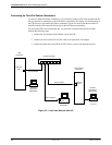
The modified cable is used to connect the network hubs together.
After connecting one end of the modified cable to a port in the first network hub, connect the other
end to a port in the second hub. Then, for each full-feature workstation, perform the following
steps:
1. Connect one end of the 035-0116-5031 cable to the EtherLink II card in the full-feature
workstation.
2. Connect the other end of the 035-0116-5031 cable to a port on the network hub unit.
Basic-Feature Workstation
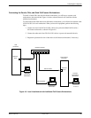
Basic-feature workstations can be connected to the host processor or UIP, either locally or
remotely over private or switched lines. On the Altos 5000 platform, the host processor can
support up to three basic-feature workstations. If the UIP is installed, eight more workstations or
up to a total of eleven basic-feature workstations can be supported. On the Altos 15000 platform,
the host processor supports six basic-feature workstations and UIP-1 can support twelve
basic-feature workstations to a total of eighteen basic-feature workstations.
NOTE
The 6800 Series NMS supports the AT&T 6386 and 6286 models as
basic-feature workstations. Refer to Chapter 1,
Introduction
, for a
complete model list.
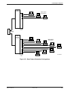
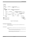
The host processor supports up to three basic-feature workstations. The fourth basic-feature
workstation, if it is to be used simultaneously, must be connected to the UIP. To support additional
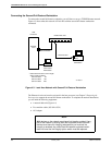
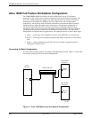
basic-feature workstations from the UIP, the optional IPC-1600 card may be required. Figure 4-10
shows this configuration.