


COMSPHERE 6800 Series Network Management System
4-38 January 1997 6800-A2-GN22-30
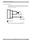
Perform the following steps at the remote end:
1. Connect the grounded end of the 035-0152-0031 cable to one of the user ports on the
System Controller or ACCULINK Network Manager.
2. Connect the other end of the 035-0152-0031 cable to the 002-0050-0031 connector.
3. Connect the 002-0050-0031 connector to the DCE device.
See Appendix A, Modem Settings, for more information on optioning 3810, 3811, 3820, or
2224CEO modems for this application.
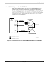
Connecting a Local Dial Backup Control Unit
To connect a local 839A DBU, you will need the following materials:
• 035-0153-0031 cable
• 002-0039-0031 connector
To establish the connection, perform the following steps:
1. Connect the grounded end of the 035-0153-0031 cable to an available port on the IPC-1600
card in the host processor or the UIP.
2. Connect the other end of the 035-0153-0031 cable to the 002-0039-0031 connector.
3. Connect the 002-0039-0031 connector to the terminal port of the 839A DBU Control Unit.
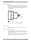
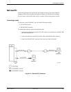
Connecting a Remote Dial Backup Control Unit
To connect a remote 839A DBU, you will need the following materials:
• 035-0153-0031 cable
• 002-0039-0031 connector
• Two DCE devices with the following characteristics:
— Asynchronous
— Full-duplex
— Flow control ON
— Bit rates of 1200, 2400, 4800, and 9600 bps
• 035-0151-0031 cable
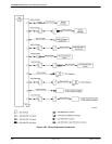
To connect a remote DBU, perform the following steps at the processor end:
1. Connect the grounded end of the 035-0153-0031 cable to an available port on the IPC-1600
card in the host processor or the UIP.
2. Connect the other end of the 035-0153-0031 cable to the 002-0039-0031 connector.
3. Connect the 002-0039-0031 connector to the local DCE devices.