


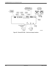

COMSPHERE 6800 Series Network Management System
2-20 January 1997 6800-A2-GN22-30
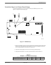
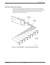
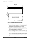
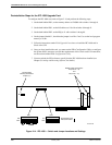
Pin 1
Pin 80
Pin 41
P3 or P4
80-Pin Header
491-13023
IPC-1600
Circuit Card
Pin 40
16-Port Ribbon Cable Assembly
Cable P4 Connects to P4 (Ports 1 – 8)
Cable P3 Connects to P3 (Ports 9 – 16)
Lead 1
Identifier
Figure 2-12. 80-Pin Headers P3 and P4 Connector Identification
5. Locate a convenient area to place the cable assembly unit close to the host processor so that
the ports are easily accessible for connecting devices. The cabinet must be located within
about seven cable feet, the length of the fanout module cable assembly, of the host
computer. The cabinet can be installed on the floor or table, or wall mounted.
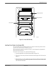
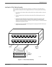
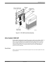
6. Route the ribbon cables behind the wire-frame assembly of the cabinet with the “lead 1”
identifiers to the left as shown in Figure 2-13. The connectors on the fanout module and the
ribbon cables are keyed for proper alignment. Be sure the retaining clips are properly
secured when connecting the ribbon cables to the fanout module.
7. Connect the ribbon cable nearest the front of the wire-frame assembly to the fanout module
connector for Ports 9 through 16. Next, connect the other ribbon cable for Ports 1 through
8.
8. The fanfold module snaps into the wire-frame assembly from the front of the assembly (see
Figure 2-13). Put the slot on the left side of the fanout module over the wire tab on the left
side of the wire-frame assembly. Next, slide the right side of the fanfold module into the
wire-frame assembly until the two slots on the right of the module engage with the wire
tabs.