


Connecting the Components
4-376800-A2-GN22-30 January 1997
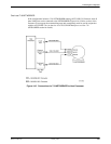
Connecting a Local System Controller
The instructions that follow apply to the DATAPHONE II System Controller as well as the
ACCULINK Network Manager.
To connect a local System Controller, you will need the following materials:
• 035-0153-0031 cable
• 002-0039-0031 connector
• 002-0051-0031 connector
• 035-0152-0031 cable
To establish the cut-throughs, perform the following steps:
1. Connect the grounded end of the 035-0153-0031 cable to the next available port on the
IPC-1600 card in the host processor or in the UIP.
2. Connect the other end of the 035-0153-0031 cable to the 002-0039-0031 connector.
3. Connect the 002-0039-0031 connector to the 002-0051-0031 connector.
4. Connect one end of the 035-0152-0031 cable to the 002-0051-0031 connector.
5. Connect the other end of the 035-0152-0031 cable to one of the user ports on the System
Controller or ACCULINK Network Manager.
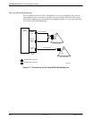
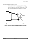
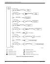
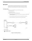
Connecting a Remote System Controller
To connect a remote System Controller or an ACCULINK Network Manager to the host processor,
you will need the following materials:
• 035-0153-0031 cable
• 002-0039-0031 connector
• Two DCE devices with the following characteristics:
— Asynchronous
— Full-duplex
— Flow control ON
— Bit rates of 1200, 2400, 4800, 9600, 19,200 bps
• 002-0050-0031 connector
• 035-0152-0031 cable
To establish the connection, perform the following steps at the processor end:
1. Connect the grounded end of the 035-0153-0031 cable to an available port on the IPC-1600
card in the host processor or the UIP.
2. Connect the other end of the 035-0153-0031 cable to the 002-0039-0031 connector.
3. Connect the 002-0039-0031 connector to one of the local DCE devices.