


Preparing the Processors
2-116800-A2-GN22-30 January 1997
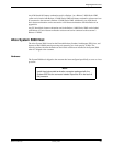
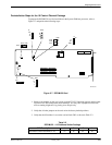
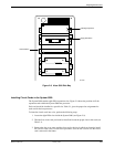
Preinstallation Steps for the 3270 Terminal Emulation Package
This upgrade package consists of an Emulex DCP-286i card, and an “octopus” cable assembly that
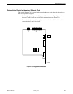
splits the signal from the board to four individual circuits. To configure the DCP-286i card, refer to
Figure 2-6 and perform the following steps:
1. Set the DIP switch labeled SW1 to the I/O address 27C.
2. Set the IRQ to 9 by positioning the jumper on the jumper pair labeled 2 on block J6. Block
J6 is on the main card, near the card edge connector below the bottom of the childboard.
Setting the jumper for IRQ 2 is the same as setting the IRQ to 9.
3. Change the settings on block J4 shown in Figure 2-6 to set the local processor block enable
jumper to disable. Move the jumper from block J4 Pins 5 and 3 to Pins 3 and 1.
4. Change the settings on jumper DEF to select 128K window size. Move the jumper from the
E and F pins to the D and E pins. No other jumper changes are required, but you should
confirm that the jumpers on the board match those in Figure 2-6.
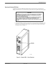
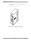
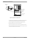
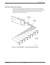
5. Follow the instructions under Optional Host Upgrade Procedures to install the DCP-286i
card in Slot 7 and to connect the octopus cable assembly.
6. When you have installed all cards in the processor, you must run the ECU to configure the
System 5000’s resources to match all circuit cards in the system. For instructions on how to
run the ECU, refer to the section EISA Configuration Utility.
7. Refer to the COMSPHERE 6800 Series Network Management System 3270 Terminal
Emulation Option Manual for instructions for loading the software.