


COMSPHERE 6800 Series Network Management System
2-36 January 1997 6800-A2-GN22-30
494-14508-01
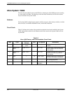
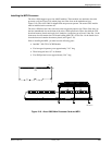
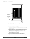
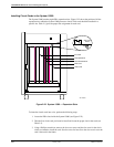
Main Processor
Card Slot
Memory
Board
Slot
S-bus
Slots
1 2 3 4
Figure 2-19. Altos 15000 Motherboard and Bus Connectors
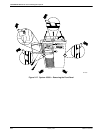
To install the MPX module, perform the following steps:
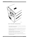
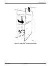
1. Using a Phillips screwdriver, remove the screw from the card’s metal bracket. Save the
screw for later use. Gently disengage the card’s bus connectors from S-bus Slot 1 and slide
the card out of the chassis.
2. On the MPX module (see Figure 2-18), screw two separator posts into the top middle and
top right holes in the card. Attach the remaining three separator posts to the top left, bottom
left, and bottom right holes on the MPX module using the hexagonal nuts provided.
3. Make sure that the jumper at J5 (see Figure 2-18) on the main processor card is placed on
Pins 2 and 3 to indicate that two CPUs are present.
4. Position the MPX module with its connector mating with the J2 connector (see
Figure 2-18) on the main processor card and press firmly until the connector is fully seated.