10 MicroMAX System User Manual Version 6.C
Camera
Introduction: The function of the camera is to collect very low intensity light and
convert the energy into a quantitative, electronic signal (photo-electrons) over a two
dimensional space. To do this, light from the subject is focused onto a CCD array, which
accumulates photoelectrons for the exposure time. At the end of the exposure time, the
image thus formed is read out. The accumulated charge on each cell of the array is
transferred out of the CCD array, amplified, and sent to the controller as an analog signal,
where it is digitized prior to transfer to the computer.
The camera is highly integrated, containing the shutter (if applicable) and thermoelectric
cooler with optional forced-air supplem
ental cooling in a single, shielded housing.
Surface mount electronic technology is used wherever possible, giving a compact
package with uncompromising performance.
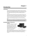
Depending on your application, the camera included in your MicroMAX system will be
either a com
pact round camera head or a high performance, cooled, rectangular camera
head. The round head features interline CCDs; its small size ensures that the camera can
be mounted on virtually any microscope port, including those found on inverted
microscopes. The rectangular head features back-illuminated CCDs with frame transfer
readout.
At the heart of the camera is the CCD array centered on the optic axis. Available form
ats
include the:
• EEV CCD57-10, 512×512, 13×13µm pixels for the MicroMAX:512BFT
• EEV CCD47-10, 1024×1024, 13×13µm pixels for the MicroMAX:1024B
• Sony ICX075, 782×582, 8.3× 8.3µm pixels for the MicroMAX:782Yand the
MicroMAX:782YHS systems
• Sony ICX061,1300×1030, 6.7× 6.7µm pixels for the MicroMAX:1300Y, the
MicroMAX:1300YHS, and MicroMAX:1300YHS-DIF systems
A special clocking mode to minimize background signal is supported. See the Princeton
Instruments brochures and data sheets for detailed specifications.
Cooling System: MicroMAX cam
eras have a multi-stage Peltier type cooler that is
thermally coupled to the CCD surface. Heat is sequentially transferred through the Peltier
stages and from there to the outer shell of the camera via a heat transfer block. This
cooling system allows the camera to maintain CCD temperature of typically -15°C for
round cameras head and -45°C for rectangular camera heads. Cameras equipped with a
fan assembly can reach lower CCD temperatures for reduced thermal noise and extended
exposure times.
Low Noise Readout: In order to achieve a low-noise readout of the CCD, several
design features have been im
plemented. These include cooling the preamplifier on the
CCD, isolating circuits to prevent electronic crosstalk and minimizing the path lengths of
critical electronic circuits. The net result of these design features is the lowest available
readout noise at the highest speed possible for these CCDs.
Controller
Data Conversion: The controller accepts the analog data and converts it to digital data
using specially designed, low-noise electronics supporting scientific grade 12- or 16-bit
Analog to Digital (A/D) converters.


