


142 MicroMAX System User Manual Version 6.C
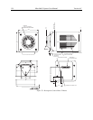
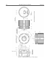
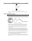
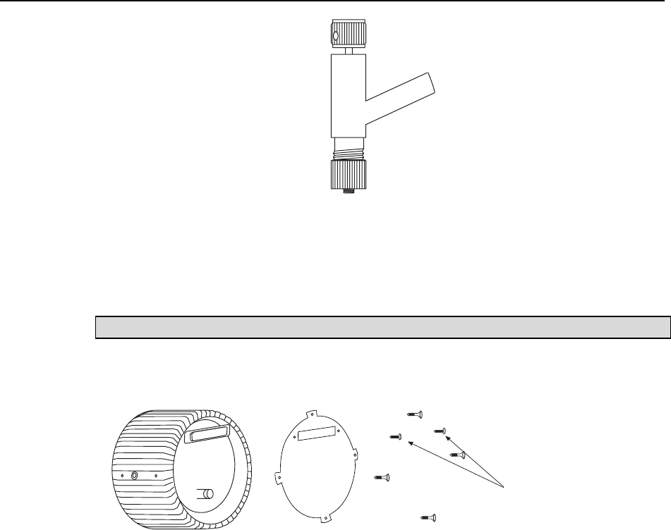
Figure 85. Vacuum Connector Required for Pumping
• Phillips screwdriver and a 3/16" nut driver, required to remove the back plate from
the camera.
Vacuum Pumpdown Procedure
The instructions that follow are for a 1 MHz or 100kHz/1 MHz round head camera only.
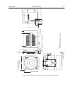
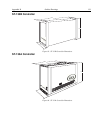
1. Remove the back cover of the camera (see Figure 86). It is secured by four Phillips-
head screws and by the two connector slide-latch posts, which can be removed using
a 3/16" nut driver.
Use a 3/16” nut driver
to remove these two screws
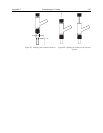
Figure 86. Removing the Back Panel
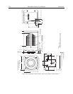
2. Push the Vacuum Connector onto the vacuum port on the back of the camera (see
Figure 87). Tighten the bottom knurled ring (the one closest to the camera body).
3. Connect the vacuum
system to the open tube and begin pumping. The vacuum
equipment should first be pumped down to a reasonable level before the camera
vacuum is opened.
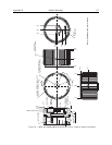
4. After a reasonable vacuum
level is reached (~20 mTorr), turn the top knob of the
Vacuum Connector clockwise a few turns. While holding the body of the connector, pull
up on the top knurled knob until it stops (see
Figure 88). This opens the camera to the
vacuum
system, and a change in vacuum pressure in the system should be observed.
5. Pum
p down to 10 mTorr or as close as possible. Overnight pumping may be required.
6. When this level has been achieved, push the top knob all the way
in until it stops.
The vacuum block is now sealed. Turn the same knob counterclockwise several
turns, to free the plug from the Vacuum Connector.
7. Rem
ove the vacuum system from the Vacuum Connector. While turning the top knob
counterclockwise, remove the Vacuum Connector from the camera. Replace the back
cover.