


Chapter 5 Operation 59
on-screen indication allows easy verification of temperature lock. In addition, the TEMP
LOCK indicator on the back of the controller lights GREEN to indicate that lock has
been achieved (for more information, refer to the description of the ST-133 rear panel
features, page
20).
The deepest operating temperature for a system depends on the CCD array size, the CCD
packaging, the am
bient temperature, and the type of cooling. The time required to
achieve lock can vary over a considerable range, depending on such factors as the camera
type, CCD array type, ambient temperature, etc. Typically, the larger the array or the
warmer the ambient temperature, the longer the time to reach lock. Once lock occurs, it is
okay to begin focusing. However, you should wait an additional twenty minutes before
taking quantitative data so that the system has time to achieve optimum thermal stability.
MicroMAX CCDs typically have the following temperature ranges:
• Better than -15°C with passive cooling and under vacuum
• Better than -30°C with the optional forced air accessory
and under vacuum
Note: If you are using the USB 2.0 interface, the Detector Temperature dialog box will
not display temperature information while you are acquiring data.
ADC Offset (Bias)
With the camera completely blocked, the CCD will collect a dark charge pattern,
dependent on the exposure time and camera temperature. The longer the exposure time
and the warmer the camera, the larger and less uniform this background will appear. This
background can be dealt with in a couple of ways: background subtraction, in which a
background image is acquired and then subtracted from an illuminated image, or by
offsetting the baseline so that much of the background is ignored during analog-to-digital
conversion (ADC).
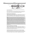
The baseline offset is a voltage that is added to the signal to bring the A/D output to a
non-zero value, ty
pically 50-100 counts. This offset value ensures that all the true
variation in the signal can really be seen and not lost below the A/D “0” value. Since the
offset is added to the signal, these counts only minimally reduce the range of the signal
from 65535 (16-bit ADC) to a value in the range of 50-100 counts lower.
Notes:
1. Do not be concerned about either the DC level of this background or its shape unless
it is very high (i.e., 400 counts). What you see is not noise. It is a fully subtractable
readout pattern. Each CCD has its own dark charge pattern, unique to that particular
device. Every device has been thoroughly tested to ensure its compliance with
Princeton Instruments' demanding specifications.
2. The baseline can be adjusted by using the F and S Zero pots located on the rear panel
of the controller. If these pots are not present, the baseline may be software-
adjustable.
3. Do not adjust the offset values to zero or some low-level data will be missed.