


88 MicroMAX System User Manual Version 6.C
widely available and can often be obtained locally, such as at a nearby Radio Shack
®
store. A list of possibly useful items follows. Note that, although the item
s listed may be
•
male type D-subminiature solder type connector (Radio Shack part no 276-
• BNC connector(s) type UG-88 Male BNC connector (Radio Shack part no 278-103).
following paragraphs. This
1. o Shack
k.
3.
er line to pin 9 (TTL OUT 1). Then apply
4. connector in a Shielded Metalized hood (Radio Shack part no 276-
6. NC connector (UG-88 Male BNC connector) to the free end of the cable
8. d
.
9.
V.
ber of lines to be monitored, it
becomes more convenient to consider using a multiple conductor shielded cable rather
than individual coaxial cables.
appropriate in many situations, they might not meet your specific needs.
25-pin fe
1548B).
• RG/58U coaxial cable.
• Shielded Metalized hood (Radio Shack part no 276-1536A).
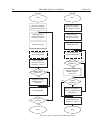
Example
Suppose you needed to build a cable to monitor the line TTL OUT 1. One approach
would be to build a cable assembly as described in the
procedure could easily be adapted to other situations.
Begin with a 25-pin fem
ale type D-subminiature solder type connector (Radi
part no 276-1548B). This connector has 25 solder points open on the bac
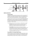
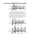
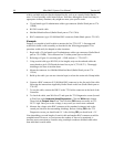
2. Referring to Figure 41, note that pin 8 = GND and pin 9 = TTL OUT 1.
Using coaxial cable ty
pe RG/58U (6 feet length), strip out the end and solder the
outer sheath to pin 8 (GND) and the inn
shielding to the lines to insulate them.
Mount the
1536A).
5. Build up the cable (y
ou can use electrical tape) to where the strain relief clamp holds.
Connect a B
following the instructions supplied by Radio Shack on the box (Radio Shack part no
278-103).
7. To use this cable, connect the DB-25 to the TTL In/Out connector on the back of the
Controller.
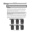
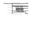
To check the cable, start WinView/32 and open the TTL Diagnostics screen (locate
in WinView under
Hardware Setup|Diagnostics). Click the Write radio button
Then click the Output Line 1 box. Next click the OK button to actually
set TTL
OUT 1 high. Once you set the voltage, it stays until you send a new command.
Measure the voltage at the BNC connector with a standard voltmeter (red on the
central pin, black on the surrounding shielding). Before clicking OK at the TTL
Diagnostics screen y
ou should read 0 V. After clicking OK you should read +5
Note that adding a second length of coaxial cable and another BNC connector would be
straightforward. However, as you increase the num