


70 MicroMAX System User Manual Version 6.C
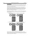
Software Binning
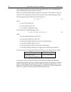
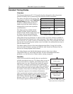
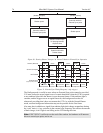
One limitation of hardware binning is that the shift register pixels and the output node are
ty
pically only 2-3 times the size of imaging pixels as shown in Table 10. Consequently, if
the total charge binned together exceeds the capacity
of the shift register or output node,
the data will be corrupted.
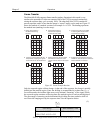
This restriction strongly limits the number of pixels that may be binned in cases where there
is a sm
all signal superimposed on a large background, such as signals with a large
fluorescence. Ideally, one would like to bin many pixels to increase the S/N ratio of the weak
peaks but this cannot be done because the fluorescence would quickly saturate the CCD.
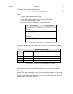
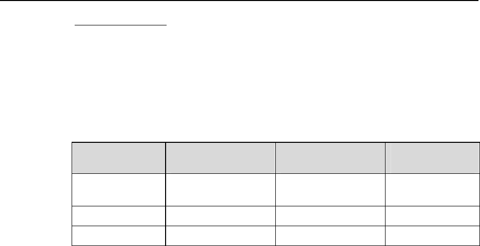
CCD Array
Imaging/Storage
Cells Well Capacity
Readout Register
Well Capacity
Output Node
Well Capacity
EEV CCD-37
512 x 512
100 x 10
3
electrons 200 x 10
3
electrons
400 x 10
3
electrons
PID 582 x 782 18 x 10
3
electrons 40 x 10
3
electrons 40 x 10
3
electrons
PID 1030 x 1300 34 x 10
3
electrons 34 x 10
3
electrons 65 x 10
3
electrons
Table 10. Well Capacity for some CCD Arrays
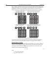
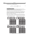
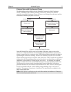
The solution is to perform the binning in software. Limited hardware binning may be
used when reading out the CCD. Software binning allows you to perform additional
binning during the data acquisition process, producing a result that represents many more
photons than was possible using hardware binning.
Software averaging can improve the S/N ratio by as much as the square root of the
num
ber of scans. Unfortunately, with a high number of scans (i.e., above 100) camera 1/f
noise may reduce the actual S/N ratio to slightly below this theoretical value. Also, if the
light source used is photon-flicker limited rather than photon shot-noise limited, this
theoretical signal improvement cannot be fully realized. Again, background subtraction
from the raw data is necessary.
This technique is also useful in high light level experiments, where the camera is again
photon shot-noise lim
ited. Summing multiple pixels in software corresponds to collecting
more photons, and results in a better S/N ratio in the measurement.
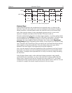
Analog Gain Control
Analog gain control is used to change the number of electrons required to generate an
Analog-to-Digital Unit (ADU, also known as a count). In WinView/32, the choice of
analog gain settings varies depending on the CCD array and the number of output
amplifiers. If your camera is not designed for analog gain selection, these settings will not
be accessible in the software.
In WinView (version 2.X and higher), analog gain selection is made on the
Acquisition|
Experiment Setup…|ADC
tab card. If there is no Analog Gain parameter on that tab
card, analog gain may not be selectable or it may be controlled by a gain switch on the
camera. When software-selection of Analog Gain is available, the software selection will
override any hardware setting that may be selected at the camera.
The analog gain of the camera should generally be set so that the overall noise is ~1
count RMS. In m
ost instances this will occur with the switch set to Medium. In
situations where the A/D range exceeds that of the array, it will generally be better to set