Chapter 4 System Setup 39
Selecting the Shutter Setting
The Shutter Setting push switch on the rear of the Controller sets the shutter hold voltage.
Each shutter type, internal or external, requires a different setting. Consult the table
below for the proper setting for your shutter. The Shutter Setting is correctly set at the
factory for the camera’s internal shutter if one is present.
Caution
Shutter Setting* Shutter Type
1 25 mm Princeton Instruments supplied External shutter
(typically an Entrance slit shutter)
2 25 mm Princeton Instruments Internal shutter
4 35 mm Princeton Instruments Internal shutter (requires 70
V Shutter option)
5 40 mm Princeton Instruments Internal shutter (supplied
with LN camera having a 1340 × 1300 or larger CCD)
* Shutter settings 0, 3, and 6-9 are unused and are reserved for future use.
Table 5. ST-133 Shutter Setting Selection
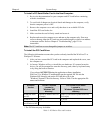
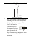
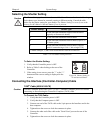
To Select the Shutter Setting:
1. Verify
that the Controller power is OFF.
2. Refer to Table 5 when looking at the rear of the
Controller.
3. If the setting is not correct, press the "-" or the "+"
button until the correct setting is display
ed in the
window.
SHUTTER CONTROL
REMOTE
SETTING
2
-
+
Figure 10. Shutter Setting for
25 mm Internal Shutter
Connecting the Interface (Controller-Computer) Cable
TAXI
®
Cable (6050-0148-CE)
Turn the Controller power OFF (OFF = 0, ON = |) and the Computer power OFF before
connecting or disconnecting the Controller-Computer (TAXI) cable.
Caution
To Connect the TAXI Cable:
1. Verify
that the Controller power is OFF.
2. Verify
that the Computer power is OFF.
3. Connect one end of the TAXI cable to the 9-pin port on the Interface card in the
host com
puter.
4. Tighten down the screws to lock the connector in place.
5. Connect the other end of the cable to the "Serial Com
" port on the rear of the
Controller.
6. Tighten down the screws to lock the connector in place.


