20 MicroMAX System User Manual Version 6.C
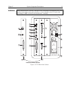
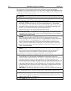
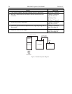
The descriptions of the rear panel connectors are keyed to the accompanying figure.
Depending on your system, either the TAXI or the USB 2.0 Interface Control Module will be
installed in the second from the left slot (as you face the rear of the ST-133). In
Figure 3, the
TAXI m
odule is shown in that position.
# Feature
1. Temperature Lock LED: Indicates that the temperature control loop has locked and that
the temperature of the CCD array will be stable to within ± 0.05°C.
2. Video/Aux Output: Composite video output is provided at this connector; if labeled Aux,
this output is reserved for future use. The Video output amplitude is 1 V pk-pk and the
source impedance is 75 Ω. Either RS-170 (EIA) or CCIR standard video can be provided
and must be specified when the system is ordered. The video should be connected to the
monitor via 75 Ω coaxial cable and it must be terminated into 75 Ω.
Note that video output is not currently supported under USB 2.0.
3. External Sync Input: TTL input that has a 10 kΩ pullup resistor. Allows data acquisition
and readout to be synchronized with external events. Through software, positive or negative
(default) triggering can be selected.
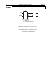
4. Output WinX/32 (ver. 2.4 and higher) software-selectable NOT SCAN or
SHUTTER signal. Default is SHUTTER. NOT SCAN reports when the controller is
finished reading out the CCD array. NOT SCAN is high when the CCD array is not being
scanned, then drops low when readout begins, returning to high when the process is
finished. The second signal, SHUTTER, reports when the shutter is opened and can be
used to synchronize external shutters. SHUTTER is low when the shutter is closed and
goes high when the shutter is activated, dropping low again after the shutter closes. See
Figure 4 for timing diagram.
5. Output: Initially HIGH. After a Start Acquisition command, this output changes
state on completion of the array cleaning cycles that precede the first exposure. Initially
high, it goes low to mark the beginning of the first exposure. In free run operation it
remains low until the system is halted. If a specific number of frames have been
programmed, it remains low until all have been taken, then returns high.
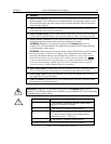
6. Zero Adjustment: (1 MHz and 100kHz/1 MHz systems) Control the offset values of the
Fast (F) and Slow (S) A/D converters; if potentiometers are not present, bias may be
software-settable. Preadjusted at factory. The offset is a voltage that is added to the signal to
bring the A/D output to a non-zero value, typically 50-100 counts. This offset value
ensures that all the true variation in the signal can really be seen and not lost below the A/D
“0” value. Since the offset is added to the signal, these counts only minimally reduce the
range of the signal from 4095 to a value in the range of 50-100 counts lower. Adjusting a
potentiometer clockwise increases the counts while rotating it counterclockwise decreases
the counts. If potentiometers are not present, bias may be software-settable.
CAUTION: Do not adjust the offset values to zero, or some low-level data will be missed.
7. Detector Connector: (1MHz and 1 MHz/100kHz systems) Transmits control information
to the camera and receives data back from the camera via the Detector-Controller cable.
8. TTL In/Out: User-programmable interface with eight input bits and eight output bits that
can be written to or polled for additional control or functionality. Output is not currently
supported under USB 2.0. See Chapter 6.
9. AUX Output: Reserved for future use.


