36 MicroMAX System User Manual Version 6.C
allow the user to reduce exposure times, increasing temporal resolution and reducing
photodamage to the living specimen.
Another method to minimize photodamage to biological preparations is to synchronize a
shutter on the excitation pathway to the exposure
period of the camera. This will limit
m
ing
nt. The C-mount employs a standard size thread to connect to the
e adapter while the F-mount uses a tongue and groove type mechanism to
exposure of the sample to the potentially damaging effects of the excitation light. Ti
and sy
nchronization are explained in Chapter 6.
The camera is connected to the microscope via a standard type mount coupled to a
microscope specific adapter piece. There are two basic camera mounting designs, the
C-mount and the F-mou
camera to th
make the connection.
C-Mount
For a camera equipped with a C-mount thread, use the standard C-mount adapter supplied
by the microscope manufacturer to attach the camera to the microscope. The adapter can
be screwed into the camera and then the assembly can be secured to the microscope using
the standard setscrews on the microscope. The camera can be mounted on the trinocular
output port, the side port, or the bottom port of the inverted microscope. When mountin
the larger cameras perpendicular to the microscope on the side port, it is ADVISED that
you provide some additional support for your camera to reduce the possibility of
vibrations or excessive stress on the C-mount nose. For the bottom port of the inverted
microscope, the C-mount is designed to support the full weight of the camera, however,
IT IS ADVISED that you provide some additional support for the larger cameras since
the camera is in a pos
g
ition where it could be deflected by
the operator’s knee or foot. This
ires a relay lens. In addition, all optical surfaces should be free from dust
rints, since these will appear as blurry regions or spots and hence degrade the
kind of lateral force could damage the alignm
ent of the nose and result in sub-optimal
imaging conditions.
Most output ports of the microscope do not require additional optical elements to collect
an image, however please check with your microscope manual to determine if the chosen
output port requ
and fingerp
image quality.
F-Mount
For a camera with the F-mount type design, you will need two elements to mount the
camera on your microscope. The first element is a Diagnostic Instruments Relay Lens.
This lens is usually a 1X relay lens that performs no magnification. Alternatively, you
may use a 0.6X relay lens to partially demagnify the image and to increase the field of
view. There is also a 2X relay lens available for additional magnification. The second
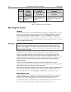
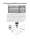
element is a microscope specific Diagnostic Instruments Bottom Clamp. shows
which bottom clamps are routinely used with each of the microscope types. They are
Table 4
illustrated in Figure 8. If you feel that you have received the wrong type of clamp, of if
y
ou need a clamp for a microscope other than those listed, please contact the factory.
To assemble the pieces, first pick up the camera and look for the black dot on the fron
surface. Match this dot with the red dot on the side of the relay lens. Then engage the two
surfaces and rotate them until the F-mount is secured as evidenced by a soft clicking
sound. Next place the long tube of the relay lens into the bottom clamp for your
microscope, securing it to the relay lens with the three setscrews at the top of the clamp
as shown in
t
9
. This whole assembly can now be placed on the microscope, using
Figure


