F-1Appendix
APPENDIX F
HARDWARE JUMPER CONFIGURATION
Jumpers on the DCU (Data Control Unit) board are used to select a few configuration paĆ
rameters. These jumpers are installed for normal operation at the factory. However, certain
applications may require a modification to the jumper configuration. To change any of these
configuration
jumpers, the DCU logic board
must be removed. T
able F-1 describes the jump
Ć
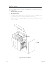
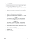
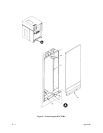
er configurations. To gain access to the DCU Printed Circuit Board Assembly (PCBA), the
right
side panel and the card cage access panel must be removed as described in the following
procedures.
- CAUTION -
Some configurations require cutting an etch and soldering on the PCBA. These
changes should only be performed by a trained technician.
- VORSICHT -
Manche Konfigurationen benötigen einen Ätzschnitt und Löten am PCBA. Diese
Änderungen sollten nur von einem geschulten Techniker vorgenommen werden.
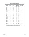
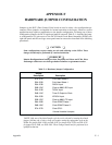
Table F-1. Hardware Jumper Configuration
Jumper
Description Description
E1A-E1B
E4A-E4B
E4B-E4C
E5A-E5B
E5B-E5C
E6A-E6B
E6B-E6C
E7A-E7B
E3A-E3B
E3B-E3C
E2A-E2B
Print
Head Select 0
Print Head Select 1
RX
CLK Input
Clock to 68901 RC Input
TX
CLK Input
T
imer C Output to Clock
NTX
CLK Input
Clock to 68901 T
C Input
Clock DPMC Phase 1
Clock DPMC Phase 2*
Clock CPU*
*Normal Installed Jumpers
*NOTE: Only one of the Serial Interface clocks can be selected by inserting the related
jumper. Selecting one of these clocks will require cutting the appropriate etch on the
PCBA:
F
or jumper E4A-E4B, cut E4B-E4C
; for jumper E5A-E5B, cut E5B-E5C
;
for jumper E6A-E6B, cut E6B-E6C. These changes should only be performed by a
qualified
technician.


