Graphics4-4
the
same as in the Single Density mode. Double horizontal density requires twice the
number
of input data bytes to print
the same length line as for Single Density. P
rintĆ
ing
double density reduces the printing speed by half.
D
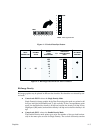
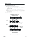
Control code ESC Y
selects the
Double Speed, Double Density Mode.
When the Double Density, Double Speed control code is received, the data will be
printed at double the current horizontal dot density, but adjacent dots are not
printed. Since Double Density graphics are printed at half speed, Double Speed,
Double
Density graphics
are printed at the same speed as are Single Density graph
Ć
ics.
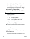
D Control
code ESC Z
selects the
Quadruple Density Mode.
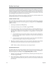
When printing Quadruple Density graphics, the printer pairs adjacent quadruple
density
bit image bytes. The compounded data is then printed in the Double Density
mode.
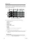
Bit Image Programming Format
The
general Bit Image expression is:
ESC CC(n1)(n2)DATA
where:
ESC =
the Serial Matrix compatible header
CC =
K, L, Y or Z to select dot density
(K=single, L=double, Y=double-density, double speed
Z=quadruple density)
n1, n2
=
n1 + 256 n2 defines the number of data bytes to follow
DATA =
the dot pattern bytes
D
The syntax of the Bit Image expression must be correct.
D The expression must include the appropriate dot density control code, the number
of
bytes of data to be plotted, and the data itself.
D
The number of data bytes and the n1, n2 definition must be equal.
D Any characters following n1 and n2 will be interpreted and plotted as data until the
n1,
n2 definition is satisfied.
D
If n1 = n2 = 0, then control codes K, L, Y, or Z are ignored.
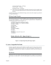
n2 = 700/256 = 2
n1 = 700-(2x256) = 700-514 = 188
The program statement is: ESC K (188)(2)(D
ATA)
NOTE:
Depending on the host computer system, it may be necessary to include a width
statement within the BASIC program.
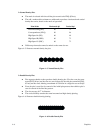
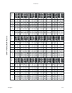
D The
maximum number of data bytes that can be included in the D
AT
A portion of the
program statement (when using 132 column paper) varies according to the
operating
mode:


