


Vertical Format Units5-10
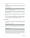
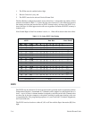
Table 5-6.
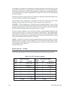
P-Series D
VFU Line Slewing
ASCII Lines Slewed
Hex PI 7 6 5 4 3 2 1
1
1
1
1
1
1
1
1
1
1
1
1
1
1
X
X
X
X
X
X
X
X
X
X
X
X
X
X
X
X
X
X
X
X
X
X
X
X
X
X
X
X
1
1
1
1
1
1
1
1
1
1
1
1
1
1
0
0
0
0
0
0
0
0
1
1
1
1
1
1
0
0
0
0
1
1
1
1
0
0
0
0
1
1
0
0
1
1
0
0
1
1
0
0
1
1
0
0
0
1
0
1
0
1
0
1
0
1
0
1
0
1
1
2
3
4
5
6
7
8
9
10
11
12
13
14
Dec
X = Undefined, 0 or 1 1 = High 0 = Low
8
X
X
X
X
X
X
X
X
X
X
X
X
X
X
1
1
0
0
0
0
1
1
1
1
1
1
1
1
0
1
15
X
X
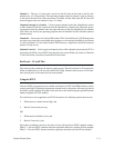
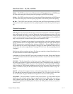
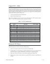
Data Bits
Code
0 = CR*
10
11
12
13
14
15
16
17
18
19
1A
1B
1C
1D
1E
16
17
18
19
20
21
22
23
24
25
26
27
28
29
30
DLE
DC1
DC2
DC3
DC4
NAK
SYN
ETB
CAN
EM
SUB
ESC
FS
GS
RS
1F 31 US
*treated as CR = CR; refer to the Carriage R
eturn control code on page 6-16.
NVFU
The
NVFU may be selected in P-Series protocol. A
maximum of 13 channels can be assigned
to
a form up to 256 lines. A channel number is assigned to each line on the form. Channel codes
are then sent by the host computer to the printer resulting in rapid paper slewing to the next
corresponding line. The programming sequence is 1) start load code; 2) LPI byte; 3) channel
assignments;
and 4) end load code.
Start Load Code - 6D Hex
The NVFU start load code is 6D hex with the Paper Instruction (PI) Line high. After the LPI
byte,
subsequent data received is channel assignment data until the end load code is received.
LPI Byte
The
first byte received after the start load code must be the Lines P
er Inch, LPI byte, not a chan
Ć
nel assignment byte.
Bit
5 of the LPI byte determines the line spacing for the form. If bit 5 of the
LPI byte is high (1), line spacing is set to 8 lpi; otherwise, the line spacing is set to 6 lpi. The
channel
number of the LPI byte is ignored (it is not a channel assignment byte), but the byte is
counted
as one of the total line bytes.