


3-7Configuration
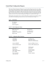
Control Panel Configuration Diagram
The
Control P
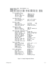
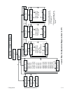
anel Configuration Diagram is a series of block
diagrams that show the configu
Ć
ration
menus and the parameters (values) available within each menu. The boxes represent
the
message
display, the message that appears on the display is printed inside the box, and the let
Ć
ters outside the boxes adjacent to the directional arrows represent control panel switches.
When a switch is pressed, an arrow leads to the displayed result of pressing that switch. The
symbols
used on the Control P
anel Configuration Diagrams are summarized in Figure 3-2.
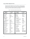
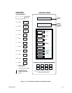
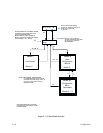
The
diagram is presented in 3 levels, each level illustrating a particular set of parameter menus
and
values. The relationships between the three levels are summarized in Figure 3-3.
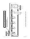
Level I - P
rint F
ormat
Line Spacing
P
rint Mode
F
orms L
ength Set
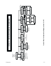
Level II - Main Configuration Menus
Ribbon Life xxx %
Host Interface
Character Set
L
oad P
arameters
Application Compatibility
Save Parameters
P
aper F
ormat Diagnostics
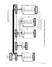
Level III - Configuration Menu P
arameters
New Ribbon
Set Ribbon Size
Set Job R
ate
When W
orn A
ction
Analyze Job
Ribbon Life Enable/Disable
Select Set IBM PC
Select Set ECMA 94 L
atin 1
Select Set Multinational
Select Set DEC Multinational
P
rinter P
rotocol Unidirectional
Buffer Size
Select SFCC
P
rinter Select
Control Code 06
P
aper A
dvance Switch
Control Code 08
80 - 9F Hex Overstrike
P
ower-On State
Display L
anguage
Alarm On F
ault