


5-3Vertical Format Units
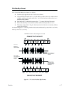
Channel 1 - The top-of-form code, reserved as the first line on the form or the first line
printed
(top-of-form position). The operating program sends the
channel 1 code to advance
to the top of the next form. After the memory is loaded, a Form Feed code (FF, 0C hex) will
move
the paper tothe next channel 1 (top-of-form).
Channels
2 through 11, 13 and 14
- Used as general channel codes (line identification codes)
or
filler channels. Each line on the form must be identified by a channel code. When the operat
Ć
ing program sends the channel code, the paper advances to the line identified by the channel
code. Lines not used by the operating program must be identified by filler channels (unused
channel
codes).
Channel
12
- R
eserved as the V
ertical T
ab channel. The V
ertical T
ab code (VT
, 0B hex) prints
any
data in the print buffer and rapidly
slews the paper to the next line identified by the channel
12 code. If channel 12 is not loaded in the EVFU memory, a single line feed will be executed
when
a VT code is sent.
Channel 15 and 16 - Used as general channel codes or filler channels only when the VFU is
accessed
by the PI line. In an EVFU form that does not use the PI line, the codes for Channels
15
and 16 function as the Start L
oad and End Load codes.
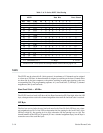
End Load - 1F or 6F Hex
The
end load code terminates the memory
load program. The end load code is 1F hex when the
PI
line
is disabled (low) or 6F hex when the PI line is high. Channel codes in excess of 192 chan
Ć
nels
received prior to the end load code are discarded.
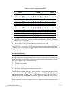
Using the EVFU
Once the EVFU program has been enabled and loaded, the VFU LOADED
indicator on the
control
panel lights. Sending the appropriate channel code to the printer will cause any data
in
the buffer to
print
and slew the paper to the next line on the form having the specified channel
number
assigned in EVFU memory.
F
or a data byte to be recognized as an EVFU instruction, the following criteria must be met:
1.
PI line must be enabled and set high; and
2.
Data bit 5 must be 0 (not set).
OR:
1.
PI line must be disabled or low; and
2.
Data bit 5 must be 1 (set).
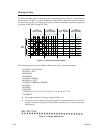
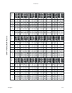
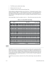
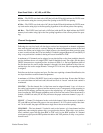
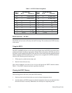
Given these conditions, the lower four bits of a byte will specify the EVFU channel number.
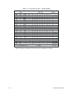
Table 5-1 lists the EVFU channels and their equivalent data bytes with the PI line enabled;
Table 5-2
lists the EVFU channel and their equivalent data bytes with the PI line disabled.