CHAPTER 2: INSTALLATION 15
Note: If user console monitor displays a message “...No Connection to Paragon… ,”
UST1 is not properly connected to the switch. Check for loose connections and use
only the recommended UTP cables (see “UTP Cabling FAQs” on page 93 for further
information).
4. Repeat steps 2 and 3 for each UST1 to be connected to the Paragon Switch user ports.
5. Connect CIM / Computer.
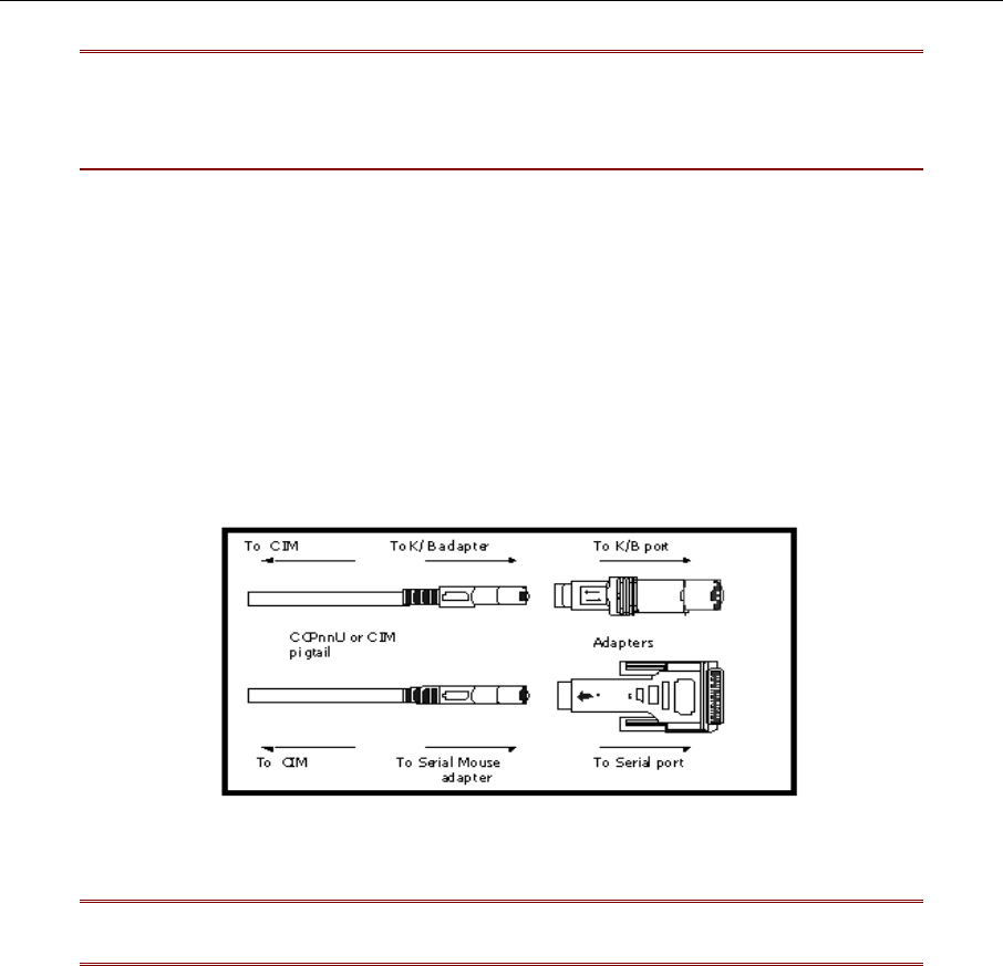
a. Connect CIM to server’s keyboard, video, and mouse ports (using part # APSAT for AT-style
PCs if needed) and power ON computer. The blinking green LED on CIM indicates proper
functioning.
b. Connect one end of a Category 5e UTP cable to Channel Port #1 on back of switch.
c. Connect the other end of cable to RJ45 port on a Computer Interface Module (CIM).
d. Power ON server.
Figure 13 APSAT – Converts AT style Keyboard and Mouse to PS/2
Note: Please refer to “Specifications” on page 85 for available CIM types, functions,
and any special installation instructions that apply for each CIM unit.


