R/C Operation
120 AX3500 Motor Controller User’s Manual Version 1.9b. June 1, 2007
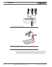
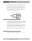
If no pulses are present, the motors are disabled, and the controller’s display will scroll
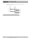
alternatively the letters “no ctrl” as shown in Figure 81 below.
After powering on the R/C radio receiver and transmitter, and if the wiring is correct, the
controller will start receiving pulses. For a preset amount of time, the controller will moni-
tor the pulse train to make sure that they are regular and therefore genuine R/C radio com-
mand pulses. After that, the motors are enabled and the LEDs will display a pattern related
to the actual motor direction (see Figure , “Motor Direction Status,” on page 108).
This power-on Watchdog feature prevents the controller from becoming active from para-
site pulses and from moving the motors erratically as a result.
Similarly, if the pulse train is lost while the motors were enabled, the controller will wait a
short preset amount of time before it disables the motors. If the pulses reappear during
that time, the controller continues without any breaks. If the communication is confirmed
to be lost, the “no ctrl” message is displayed again.
Note: the Accessory Outputs C will be turned Off when radio is lost.
Important Notice about PCM Radios
PCM radios have their own watchdog circuitry and will output a signal (normally a
“safe condition” value) when radio communication is lost. This signal will be inter-
preted by the AX3500 as a valid command and the controller will remain active. To
benefit from the AX3500’s radio detection function, you will need to disable the PCM
radio watchdog.
R/C Transmitter/Receiver Quality Considerations
As discussed earlier in this chapter, the AX3500 will capture the R/C’s command pulses
with great accuracy. It will therefore be able to take advantage of the more precise joy-
sticks and timings that can be found in higher quality R/C radio, if such added precision is
desired in the application.
Another important consideration is the R/C receiver’s ability to operate in an electrically
noisy environment: the AX3500 switches high current at very high frequencies. Such tran-
sients along long battery and motor wires will generate radio frequency noise that may
interfere with the R/C radio signal. The effects may include reduced remote control range
and/or induced errors in the command pulse resulting in jerky motor operation.
A higher quality PCM R/C transmitter/radio is recommended for all professional applica-
tions, as these are more immune to noise and interference.
While a more noise-immune radio system is always desirable, it is also recommended to
layout the wiring, the controller, radio and antenna so that as little as possible electrical
FIGURE 81. “No control” message will scroll when no valid radio signal is present


