RC Pulses Output
72 AX3500 Motor Controller User’s Manual Version 1.9b. June 1, 2007
Connector Location and Pinout
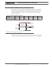
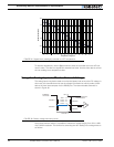
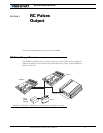
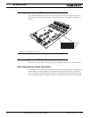
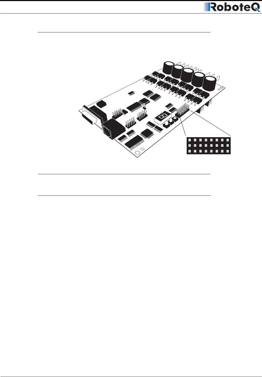
Figure 40 below shows the location of the RC Output connector and its pin assignment.
Three pins are provided for each output, matching the pinout of standard Futaba RC con-
nectors.
Connecting Servos to Controllers
Special care must be used when connecting the AX3500 to servos or to slave controller.
Servo Connection to RevA Controllers
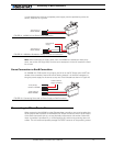
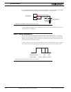
On AX3500 with PCB version prior to 3.0, the 5V rail on the RC Output pins is connected to
the controller’s internal 5V supply. The controller’s 5V power output has very limited cur-
rent drive capability of approximately 100mA for all 8 channels and can therefore be used
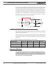
to drive directly, as shown in Figure 41, only the most efficient servos with very little load.
FIGURE 40. RC Output Connector
GND
87654321
5V Out
Pulse Out


