RC Pulses Output
74 AX3500 Motor Controller User’s Manual Version 1.9b. June 1, 2007
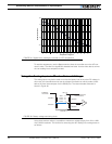
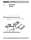
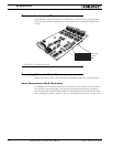
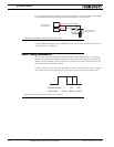
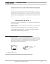
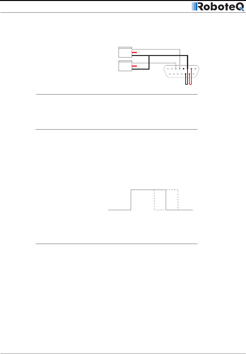
ler. The figures below shows how to make this connection. The red wire from the AX3500
to the Slave Controller may be left uncut if the red loop wire is cut instead.
A more detailed description of the AX3500 RC Input circuit can be found at “R/C Input Cir-
cuit Description” on page 115.
Pulse Timing Information
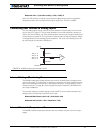
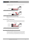
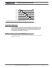
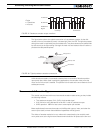
The RC Output port sends 8 pulses of programmable width ranging from 1ms to 2ms at
minimum and maximum position, respectively. Figure 45 shows the pulse’s waveform at
various command values. An RC Servo will be centered and a Slave Controller will be Off
when the pulse it at half width (1.5ms).
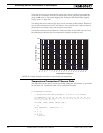
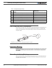
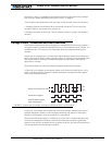
A pulse is output on each channel sequentially as show in Figure 46. As a result, the pulse
train repeat every 8ms (if all pulses are 1ms wide) to 16ms (if all pulses are 2ms wide)
1
8
9
15
To RC Outputs of
Master AX3500
Input connector o
f
Slave Controller
FIGURE 44. AX3500 to Slave Controller Connection
Command Value 0 255
Pulse Width 1.00ms 2.00ms
127
1.50ms
FIGURE 45. RC Pulse Output waveform and timing


