R/C Operation
124 AX3500 Motor Controller User’s Manual Version 1.9b. June 1, 2007
Notes:
If you attempt to calibrate the joysticks while the radio is off or not connected to the con-
troller, the calibration data will not change and the previously stored information will con-
tinue to be used.
If calibration is performed with only one R/C channel connected to the controller, then only
the joystick that is active will be calibrated. The other channel will keep its original settings.
A minimum amount of travel is required between the min, max and center joystick posi-
tions. If, while calibrating, the joystick has not been moved far enough from either side of
the center position, the controller will automatically include a minimum of travel to ensure
proper and safe operation. In most cases, this creates no undesired effect to the driving
characteristics of the robot.
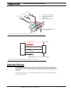
R/C calibration only applies to the channel 1 and channel 2 inputs. The accessory activation
channel (channel 3) is preset at the factory and cannot be changed.
Important Notice
To ensure that only stable pulses are present, the R/C transmitter and radio must be
On before entering joystick calibration.
Note: Channel 3 is not available on the controllers equipped with encoder inputs.
Data Logging in R/C Mode
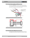
While in R/C Mode, the AX3500 will continuously send a string of characters on the RS232
output line. This string will contain 12 two-digit hexadecimal numbers representing the fol-
lowing operating parameters.
• Captured R/C Command 1 and 2
• Power Applied to Controller’s output stage
• Values applied to Analog inputs 1 and 2
• Amps on channel 1 and 2
• Internal Heat Sink temperatures 1 and 2
• Main Battery voltage
• Internal 12V voltage
• Encoder Speed or Position feedback.
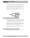
The entire string is repeated every 200 milliseconds with the latest internal parameter val-
ues. This information can be logged using the Roborun Utility (see “Viewing and Logging
Data in Analog and R/C Modes” on page 197). It may also be stored in a PDA that can be
placed in the mobile robot.
The string and data format is described in “Analog and R/C Modes Data Logging String For-
mat” on page 170. The serial port’s output can be safely ignored if it is not required in the
application.
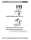
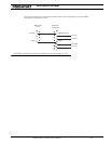
To read the output string while operating the controller with the R/C radio, you must mod-
ify the R/C cable to add an RS232 output wire and connector that will be connected to the


