AX3500 Motor Controller User’s Manual 35
Single Channel Operation
If you are using this type of motor, make sure that it is mounted on isolators and that
its casing will not cause a short circuit with other motors and circuits which may
also be inadvertently connected to the same metal chassis.
Single Channel Operation
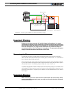
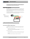
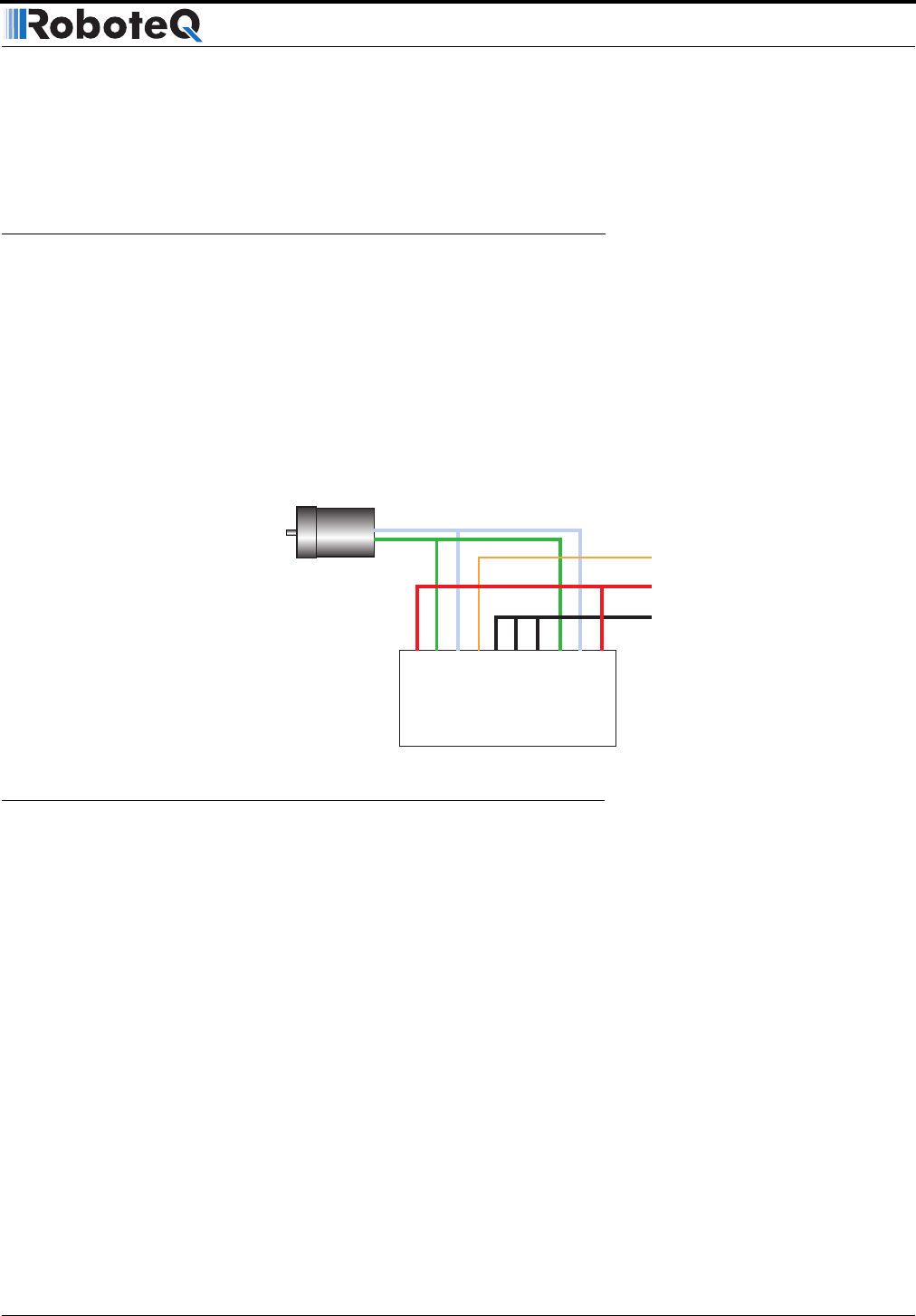
The AX3500’s two channel outputs can be paralleled as shown in the figure below so that
they can drive a single load with twice the power. To perform in this manner, the control-
ler’s Power Transistor that are switching in each channel must be perfectly synchronized.
Without this synchronization, the current will flow from one channel to the other and cause
the destruction of the controller.
The controller may be ordered with the -SC (Single Channel) suffix. This version incorpo-
rates a hardware setting inside the controller which ensures that both channels switch in a
synchronized manner and respond to commands sent to channel 1.
Converting the AX3500 to Single Channel
The AX3500 can be easily modified into a Single Channel version by placing a jumper on
the PCB. This step must be undertook only if you have the proper tooling and technical
skills.
• Disconnect the controller from power
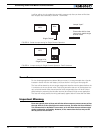
• Depending on the board’s revision, place a drop of solder on the PCB jumper pad
shown in Figure 13 or insert a jumper as shown in Figure 14.
Before paralleling the outputs,
• Place the load on channel 1 and verify that it is activated by commands on channel
1.
• Then place the load on channel 2 and verify that is also activated by commands on
channel 1.
• Commands on channel 2 should have no effects on either output.
-
+
Controller
GND
12V to 40V
Pwr Ctrl
VMot
VMot
M1-
M1+
VCon
GND
GND
GND
M2+
M2-
FIGURE 12. Wiring for Single Channel Operation
Warning:
Use this wiring only with
-SC versions (Single
Channel) of the controller


