Connecting and Using the Encoder Function
80 AX3500 Motor Controller User’s Manual Version 1.9b. June 1, 2007
Cable Length and Noise Considerations
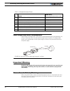
Cable should not exceed one 3’ (one meter) to avoid electrical noise to be captured by the
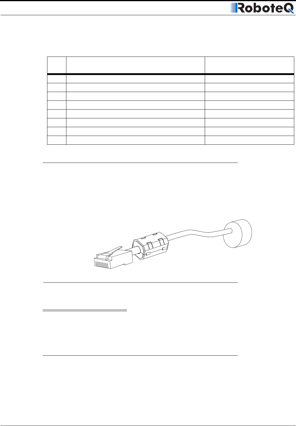
wiring. A ferrite core filter must be used for length beyond 2’ (60 cm). For longer cable
length use an oscilloscope to verify signal integrity on each of the pulse channels and on
the power supply.
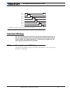
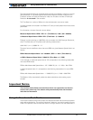
Important Warning
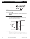
Excessive cable length will cause electrical noise to be captured by the controller and
cause erratic functioning that may lead to failure. In such situation, stop operation
immediately.
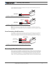
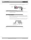
Motor - Encoder Polarity Matching
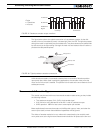
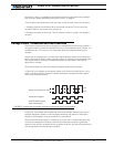
When using the Encoder module for closed loop speed control, it is imperative that when
the motor is turning in the forward direction, the counter increments its value and a posi-
tive speed value is measured.
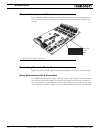
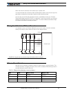
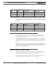
TABLE 14. Encoder Connector Pinout
Pin Name
Cable Color
(when using standard network cable)
1 Encoder 2 - Channel B. Optional Limit Switch 4 Orange/White
2 Encoder 2 - Channel A. Optional Limit Switch 3 Orange
3 Ground (same as pin 7) Green/White
4 5V Out (same as pin 8) Blue
5 Encoder 1 - Channel B. Optional Limit Switch 2 Blue/White
6 Encoder 1 - Channel A. Optional Limit Switch 1 Green
7 Ground (same as pin 3) Brown/White
8 5V Out (same as pin 4) Brown
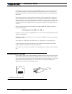
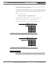
Ferrite Core
Encoder
FIGURE 50. Use ferrite core on cable length beyond 2’ or 60cm


